Table of Contents
Advertisement
Quick Links
Advertisement
Table of Contents

Related Manuals for Buchi Process Analyser PA2


Summary of Contents for Buchi Process Analyser PA2
- Page 1 Process Analyser PA2 Operation Manual...
- Page 2 Imprint Product Identification: Operation Manual (Original) Process Analyser PA2 11594012 Publication date: 09.2023 Version E NIR-Online GmbH Emil-Gumbel-Str. 1 69126 Heidelberg E-mail: info.nir-online@buchi.com NIR-Online reserves the right to make changes to this manual as required on the basis of future insights, especially with respect to layout, illustrations and technical detail.
-
Page 3: Table Of Contents
Sensor installation .......................... 21 Connecting the sensor........................ 22 Connecting the video cable (optional accessory) ................ 24 Connecting the thermostat......................... 25 5.10 Connecting the coolant ........................ 25 5.11 Establishing the electrical connection to the installation box ............. 25 Operation Manual Process Analyser PA2... - Page 4 Regular maintenance work ........................ 28 Taking out of service and disposal.................... 29 Disposal ............................. 29 Returning the instrument ........................ 29 Appendix ............................ 30 Spare parts and accessories ...................... 30 9.1.1 Accessories.......................... 30 9.1.2 Spare parts specifications.................... 30 Operation Manual Process Analyser PA2...
-
Page 5: About This Document
1.2.1 Warning symbols Symbol Meaning General warning Dangerous electrical voltage Explosive substances 1.2.2 Mandatory directive symbols Mandatory signs Meaning Read manual 1.3 Mark-ups and symbols NOTE This symbol draws attention to useful and important information. Operation Manual Process Analyser PA2 5/34... - Page 6 Buttons are marked-up like this. [Button] [Field names] Field names are marked-up like this. [Menu / Menu item] Menus or menu items are marked-up like this. Status Status is marked-up like this. Signal Signals are marked-up like this. 6/34 Operation Manual Process Analyser PA2...
-
Page 7: Safety
Damage or hazards attributable to use of the product other than as intended are entirely at the risk of the operator alone. 2.3 Location of safety notices and warning signs on the product The following safety signs and warning symbols are present on the sensor. Operation Manual Process Analyser PA2 7/34... -
Page 8: Safety Features
2.5.2 Risk of explosion from unplugging the device power plug Risk of explosion from unplugging the device power plug when the power is switched Do not unplug the sensor when the power is switched on. 8/34 Operation Manual Process Analyser PA2... -
Page 9: Staff Qualification
Technical modifications to the instrument or accessories should only be carried out with the prior written approval of NIR-Online GmbH and only by authorized NIR-Online service technicians. NIR-Online GmbH accepts no liability whatsoever for damage arising as a result of unauthorized modifications. Operation Manual Process Analyser PA2 9/34... -
Page 10: Product Description
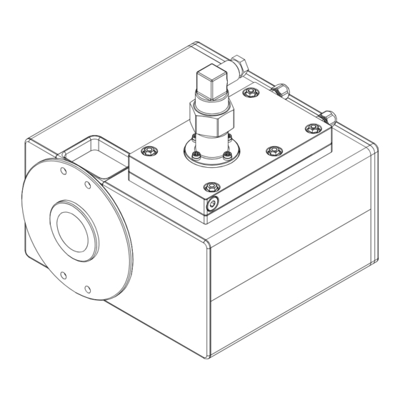
A computer program compares the data sequence curve with a calibration model and in that way determines the chemical composition of the sample. 3.2 Configuration 3.2.1 Front view Fig. 2: Front View Measurement window Flange Heat sink 10/34 Operation Manual Process Analyser PA2... -
Page 11: Rear View
Type plate Video connection Ground connection (Equipotential bonding) Device cable connection 3.3 Type plate The type plate identifies the instrument. The type plate is attached to the rear panel. See Chapter 3.2.2 "Rear view", page 11 Operation Manual Process Analyser PA2 11/34... - Page 12 The following product options are possible: Letter Option FEEDER/X-ROT (without ATEX certification) CAMERA Gold reflector (X-One) Silver reflector (X-Two/X-Four (diffusion lamps), X-Three) Lamp position rev. 1.3.2 Lamp position rev. 1.3.6 (X-Two/X-Four/X-View (diffusion lamps)) Camera setting flange (0 mm) 12/34 Operation Manual Process Analyser PA2...
-
Page 13: Atex Rating
D -: zone 21,adequate safety in event of foresee- able faults 3.5 Scope of delivery NOTE The scope of delivery depends on the configuration of the purchase order. Accessories are delivered as per the purchase order, order confirmation, and delivery note. Operation Manual Process Analyser PA2 13/34... -
Page 14: Technical Data
85 - 264 VAC 3.6.3 Ambient conditions Max. altitude above sea level 2500 m Ambient temperature -10 °C ≤ Tamb ≤ + 40 °C Max. relative air humidity < 90 % non-condensing Storage temperature max. 45 °C 14/34 Operation Manual Process Analyser PA2... -
Page 15: Materials
Optimized for NIR admin As required measurement of moving objects on a conveyor belt Control end- NIR admin As required point of mixing processes Sample move- Verify sample NIR admin As required ment detection flow Operation Manual Process Analyser PA2 15/34... - Page 16 (if not fully auto- mode) mangement mated) View results (ta- ble, trend, charts, reports) Reference data management SX-Backup Data backup Automated NIR admin During installa- scheduler backup of mea- tion surement data, results and cali- brations 16/34 Operation Manual Process Analyser PA2...
-
Page 17: Transport And Storage
Make sure that the ambient conditions are complied with (see Chapter 3.6 "Technical data", page 14). Wherever possible, store the device in its original packaging. After storage, check the device for damage and replace if necessary. Operation Manual Process Analyser PA2 17/34... -
Page 18: Installation
— The sensor is not exposed to any external sources of heat such as direct sunlight NOTE Make sure that the power supply can be disconnected at any time in an emergency. 18/34 Operation Manual Process Analyser PA2... -
Page 19: Installation Point In Piping System (Example)
Büchi Labortechnik AG Installation | 5 5.3 Installation point in piping system (example) < 1 m Fig. 5: Configuration Flow restrictor Bypass Analyser Sample removal point Flow restrictor Operation Manual Process Analyser PA2 19/34... -
Page 20: Installation (Example)
(up to 2 sensors with CCD camera per computer) 5.5 Establishing installation point The fixing points or bolts conform to M6 A2-70/7.3 Nm. Establish the installation point according to the specified data of the flange. 20/34 Operation Manual Process Analyser PA2... -
Page 21: Sensor Installation
DANGER Use of an unsuitable flange in potentially explosive atmospheres. The use of an unsuitable flange may cause an explosion. In potentially explosive atmospheres use a double flange. The following installation positions are possible: Operation Manual Process Analyser PA2 21/34... -
Page 22: Connecting The Sensor
Make sure that the power is not switched on when connecting the sensor. NOTE Loss of performance due to use of unsuitable device cables Max. cable length between installation box and sensor 10 m. 22/34 Operation Manual Process Analyser PA2... - Page 23 Plug the connector into the sensor. Secure the connector. Tightening torque: 2.5 Nm ± 0.5 Fix the cable guard to the sensor. Tightening torque: 2 Nm ± 0.5 Fix the ground cable to the sensor. Operation Manual Process Analyser PA2 23/34...
-
Page 24: Connecting The Video Cable (Optional Accessory)
5.8 Connecting the video cable (optional accessory) — Socket, 7 mm Slide the cable guard over the video cable connector. Plug the connector into the sensor. Tightening torque: 2.5 Nm ± 0.5 Fix the cable guard to the sensor. 24/34 Operation Manual Process Analyser PA2... -
Page 25: Connecting The Thermostat
Observe the legal requirements when connecting the instrument to the power supply. Use additional electrical safety features (e.g., residual-current circuit breakers) to comply with local laws and regulations. Perform installation in accordance with IEC/EN 60079-14. The power supply must fulfil the following conditions: Operation Manual Process Analyser PA2 25/34... - Page 26 Use only the power supply cables supplied with the product or ordered separately from the manufacturer. If using any other power supply cables, make sure that they match the specifications on the type plate. 26/34 Operation Manual Process Analyser PA2...
-
Page 27: Operation
Mark sample with date, time and sensor number. Carry out a laboratory analysis. Insert the reference data in the journal for creating the calibration model. See SX- Suite User Manual and SX-Plus User Manual Operation Manual Process Analyser PA2 27/34... -
Page 28: Cleaning And Servicing
If they are dirty, clean them. Replace damaged warning symbols. Optics Annually NOTICE! Have operation carried out by NIR-Online service techni- cian Replace lamps. Casing NOTICE! Have operation carried Annually out by NIR-Online service techni- cian Check and replace seals 28/34 Operation Manual Process Analyser PA2... -
Page 29: Taking Out Of Service And Disposal
When disposing, observe the disposal regulations of the materials used. Materials used see Chapter 3.6 "Technical data", page 14. 8.2 Returning the instrument Before returning the instrument, contact the NIR-Online GmbH Service Department. service.nir-online@buchi.com and ask for an RMA number. Operation Manual Process Analyser PA2 29/34... -
Page 30: Appendix
Device cables NOTE Loss of performance due to use of unsuitable device cables Max. cable length between installation box and sensor 10 m. Sensor Cable Pin assignment on device connector viewed from rear of instrument: 30/34 Operation Manual Process Analyser PA2... - Page 31 Fig. 8: Pin assignment PIN 1- blue, ground PIN 2- red, 12.7 VDC PIN 3- green, RxD- PIN 4- yellow, TxD+ PIN 5- white, TxD- PIN 6- brown, RxD+ PIN 7- not connected PIN 8- not connected Operation Manual Process Analyser PA2 31/34...
- Page 32 Pin 2 white (from green), TxD+ (B) Pin 3 orange, RxD+ (B) Pin 4 white (from orange). RxD- (A) When using the supplied Moxa D-Sub 9-pole connector, swap the cables on pin 1 and 2. 32/34 Operation Manual Process Analyser PA2...
- Page 34 We are represented by more than 100 distribution partners worldwide. Find your local representative at: www.buchi.com...
Need help?
Do you have a question about the Process Analyser PA2 and is the answer not in the manual?
Questions and answers