Table of Contents
Advertisement
Quick Links
SSV WORKS, 201 N. Rice Ave Unit A, Oxnard, CA 93030
www.SSVworks.com | Phone: 818-991-1778 | Fax: 866-293-6751
WARRANTY INFORMATION:
All SWITCH Works Electronics are covered by a limited 1 year warranty against defects in
material or workmanship. Contact SSV Works for further warranty information.
SW-E12
ELECTRONIC ACCESSORIES
SMART SWITCHER
Please read and understand these
!
instructions completely before
installation to avoid possible injury, or
damage to the accessory or vehicle.
12 OUTPUT
BY
1
Advertisement
Table of Contents

Related Manuals for SSV Works SWITCH WORKS ALPHA 12 SW-E12


Summary of Contents for SSV Works SWITCH WORKS ALPHA 12 SW-E12
- Page 1 SW-E12 12 OUTPUT ELECTRONIC ACCESSORIES SSV WORKS, 201 N. Rice Ave Unit A, Oxnard, CA 93030 SMART SWITCHER www.SSVworks.com | Phone: 818-991-1778 | Fax: 866-293-6751 WARRANTY INFORMATION: Please read and understand these All SWITCH Works Electronics are covered by a limited 1 year warranty against defects in instructions completely before material or workmanship.
-
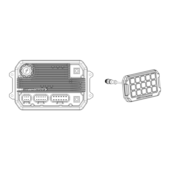
Page 2: Parts Contents
PARTS CONTENTS SWITCH Works 12 Circuit LCD Touch Button Controller Mounting Brain Module Controller Bracket RAM Mount 1” RAM Mount RAM Mount Double Brain Module Power Ball Base Ball Adapter Socket Arm Harness High Current Pigtail & Ring Terminal (x6) Low Current Pigtail (x6) High Current... -
Page 3: Connection Diagram
CONNECTION DIAGRAM USB Port (for software updates only) To Battery To Ground Low Current High Current Outputs x6 Outputs x6 Illumination NOTE: Controller MUST be connected first before power is applied to the switcher. -
Page 4: Device List
DEVICE LIST To make programming the SWITCH Works module easier, we recommend mapping your accessories with the cheat sheet below. Determine which accessory you're connecting to each individual output; which button you want to control the output (button used is not determined by output location);... -
Page 5: Installation
INSTALLATION Skip step 1 and 2 if using vehicle specific kit. 1. Attach the RAM Mount ball adapter to the Controller Mounting Bracket and secure with the 1 3/8” pan head screw and locknut. 2.Attach the Controller Mounting Bracket to the LCD Touch Button Controller using the 4 flat head, thread cut screws provided. - Page 6 INSTALLATION 5. Plug the B-H2513 harness to the SWITCH Works Brain. 6. Plug the LCD Touch Button Controller to the B-H2513 harness. 7. Tap ACC wire to a switched 12 volt power source. Tap Illumination wire to headlight power for dimming function. NOTE: LCD Touch Button Controller MUST be con- nected before applying ACC power to the switcher.
- Page 7 PROGRAMMING SWITCH Works LCD Touch Controller Button Layout The SWITCH Works LCD Touch Controller features 60 user programmable buttons and 64 icons to choose from to control electrical devices. Unit is defaulted to 1 page of 12 buttons from the factory. Additional button pages MENU can be turned on in GENERAL menu.
-
Page 8: Output Settings
PROGRAMMING OUTPUT SETTINGS Select OUTPUT number (H1 to H6 and L1 to L6) and set the power source and function for each output. Output Timer Battery Latched Disabled Back Output Power Source Description High Current Battery Output stays on with ignition (ACC) off H1 to H6 Ignition Output turns on with ignition (ACC) on... -
Page 9: Button Settings
PROGRAMMING BUTTON SETTINGS Output Button Button Button Menu Status Icon Current Limit Light Bar Next Back Back General About Page Function Button Number Select button number and set the output you want each button to turn ON or OFF. Note that a button can be set to control more than one output. -
Page 10: Status - Output
PROGRAMMING STATUS - Output Status Status Status Module Output Output 76.5 F 2.3A Short Circuit Back Back Protection The SWITCH Works LCD Touchscreen controller can show TEMPERATURE, CURRENT DRAW, STATUS (On/Off) and SHORT CIRCUIT Protection Status of each used output. CURRENT LIMIT Output Button Button Status... -
Page 11: General Settings
GENERAL SETTINGS GENERAL SETTINGS Output Button Button Temp Button Backlight Menu Status General Icon Units Level Pages Restore Restore Current Limit Crtlr Module Back About Back General Output Option Description °F Fahrenheit Temp Units °C Celsius Day (10% to 100%) Set daytime back light level Back light Level Night (10% to 100%)
Need help?
Do you have a question about the SWITCH WORKS ALPHA 12 SW-E12 and is the answer not in the manual?
Questions and answers