Onkyo TX-NR801/E Service Manual
Hide thumbs
Also See for TX-NR801/E:
- Brochure & specs (28 pages) ,
- Instruction manual (98 pages) ,
- Service manual (117 pages)
Table of Contents
Advertisement
Quick Links
SERVICE MANUAL
SERVICE MANUAL
AV RECEIVER
TX-NR801/E
MODEL
DIRECT / PURE AUDIO STEREO
SURROUND
THX
DSP
Black, Golden and Silver models
BMDD,BMDC
GMWT,GMWR
BMPP, SMPP,BMPA,GMPA
GMGK
SAFETY-RELATED COMPONENT
WARNING!!
COMPONENTS IDENTIFIED BY MARK
SCHEMATIC DIAGRAM AND IN THE PARTS LIST ARE
CRITICAL FOR RISK OF FIRE AND ELECTRIC SHOCK.
REPLACE THESE COMPONENTS WITH ONKYO
PARTS WHOSE PART NUMBERS APPEAR AS SHOWN
IN THIS MANUAL.
MAKE LEAKAGE-CURRENT OR RESISTANCE
MEASUREMENTS TO DETERMINE THAT EXPOSED
PARTS ARE ACCEPTABLY INSULATED FROM THE
SUPPLY CIRCUIT BEFORE RETURNING THE
APPLIANCE TO THE CUSTOMER.
1
SETUP
TUNING
ENTER
RE TURN
PRESET
MEMORY
FM MODE
A-FO RM LISTENING MODE MEMORY
120V, AC 60Hz
120/220~230V, AC 50/60Hz
230~240V, AC 50Hz
220V, AC 50Hz
ON THE
TX-NR801/E
Ref. No. 3785
102003
Advertisement
Table of Contents

Related Manuals for Onkyo TX-NR801/E


Summary of Contents for Onkyo TX-NR801/E
- Page 1 COMPONENTS IDENTIFIED BY MARK ON THE SCHEMATIC DIAGRAM AND IN THE PARTS LIST ARE CRITICAL FOR RISK OF FIRE AND ELECTRIC SHOCK. REPLACE THESE COMPONENTS WITH ONKYO PARTS WHOSE PART NUMBERS APPEAR AS SHOWN IN THIS MANUAL. MAKE LEAKAGE-CURRENT OR RESISTANCE...
-
Page 2: Specifications
TX-NR801/E SPECIFICATIONS AMPLIFIER SECTION TUNER SECTION Continuous average power output (FTC) (USA and Canadian mod- Tuning range els): All channels: 100 W per channel min. RMS USA & Canadian models: 87.50~108.00 MHz (100 kHz into 8 , 2 channels dri ven fr... -
Page 3: Service Procedures
TX-NR801/E SERVICE PROCEDURES 4. Memory Preservation 1. Replacing the fuses This unit does not require memory preservation batteries. A built-in memory power back-up system preserves the contents This symbol located near the fuses indicates of the memory during power failures and even when the unit is that the fuse used is fast operating type. -
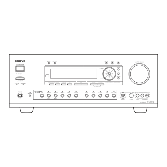
Page 4: Front Panel View
TX-NR801/E FRONT PANEL VIEW To select an input source, press the desired button MASTER VOLUME dial (REC OUT or ZONE 2) and then press one of the Use to control the volume in the main zone. The vol- input source b utton within 8 seconds. That source will ume for the remote zone (Zone 2) is independent. - Page 5 TX-NR801/E FRONT PANEL VIEW POWER switch (for all models other than SURROUND button USA, Canadian and Australian models) Selects for the Dolby Pro Logic II, DTS Neo:6, Press to turn on and off the main power supply for Dolby Digital, or DTS listening modes.
- Page 6 TX-NR801/E FRONT PANEL VIEW Here is an explanation of the controls and displays on the front panel of the TX-NR801/TX-NR801E. The specifications for your model may differ due to regional requirements. Front Panels USA, Canadian and Australian models SETUP TUNING...
-
Page 7: Rear Panel View
These jacks are for connecting to the video input jacks on tele vision monitors or projectors. COMPONENT VIDEO OUTPUT This jack is for connecting other Onkyo compo- These jacks are for connecting to the component nents equipped with the same terminal. -
Page 8: Remote Controller
TX-NR801/E REMOTE CONTROLLER The RC-511M is a multi-functional remote controller. The instructions given here only explain how to use the remote controller in conjunction with the TX-NR801/ TX-NR801E. To operate the TX-NR801/TX-NR801E using the remote controller, First press the RCVR but- ton in the MODE area to place the remote controller in the receiver mode. - Page 9 TX-NR801/E REMOTE CONTROLLER SEND/LEARN indicator Re-EQ button Lights red when signals are sent by the remote con- Depending on the listening mode, you can turn the troller. It also flashes when a button is pressed and Re-EQ function on or of f.
- Page 10 TX-NR801 EXPLODED VIEW (120V and Australian models) P901 P1010 85 94 P7201 P602 F901 P603C F902 P2901 Q6062 F903 Q6052 P7701 Q6056 F6902 F6901 T901 Q6066 Q9422B Q9422A F9501 F9502 F9504 F9503 F9501A...
-
Page 11: Block Diagram
TX-NR801/E BLOCK DIAGRAM 11dB MUTE MULTICHANNEL INPUT 11dB HEAD PHONE MUTE HPEN MASTER VOLUM E TONE PREOUT NJU7 306G LEFT Power Amplif ier BOOST MUTE +29d B SL->L C->L SW->L BYPASS TC94A07F FRON T SPEAKE RS RIGHT MUTE +29d B RIGHT SR->... - Page 12 TX-NR801/E BLOCK DIAGRAM DIGITAL AUDI O INPUT OPTI CAL VIDEO 5 DIGITAL AUDI O OUTPU T 24.576MHZ (FRONT) OPTI CAL 1 SRAM COAX IAL 1 CY7C CY7C 1019BV33 1019BV33 TC92 COAX IAL 2 OPTI CAL 2 24.576MHZ COAX IAL 3...
- Page 13 TX-NR801/E SCHEMATIC DIAGRAM 1 Display and submicroprocessor P7201A TO NAAR-8078 (SCH-9) NADIS-7746 12.0 C7501 NAETC-7749 P7481 HEADPHONES 474Z R7501220 R7502 474Z C7502 474Z C7509 104Z D7501 C7482 C7481 C7483 101J 101J MDD/MDC MPP MWT/MWR MPA UDZ11B D7502 R7276 1SS352 C7510...
- Page 14 TX-NR801/E SCHEMATIC DIAGRAM 1 Display and submicroprocessor Q7501 HNA-16MM40T OR 16-BT-115GNK 2SC2712-GR KTC3875-GR Q7503 Q7504 (SCH.7) BLACK GOLD SILVER JL7201A D7536 GREEN ORANGE OGANGE D7537 GREEN ORANGE ORANGE D7538 GREEN ORANGE ORANGE D7539 GREEN ORANGE ORANGE M66005-0001FP S7543 S7541 AUDIO SEL...
- Page 15 TX-NR801/E SCHEMATIC DIAGRAM 2 DSP and Main microprocessor sections NADG-7687 P701 DSP1GP8" R7102 DSP1GP9" DSP1GP10" R7103 C706 104Z VSS1 1 VDDI 3 60 Q706 R730 1K Q705 CY7C 1019BV33 -15VCT CY7C 1019BV33 -15VCT INT1" EXLOCK 59 MOD0 58 MOD1 57...
-
Page 16: Schematic Diagram
TX-NR801/E SCHEMATIC DIAGRAM 2 DSPDA RDSDET DSPCL TO POWER AMP. VIA (SCH.7) P7701A Q180 LC72723M 220K L180 +5VDSP DSP and Main KRC1 04S Q7001 RN14 04 C7004 1/50 microprocessor CSTC V16.0MXJ UDZ6 .2B sections D700 5 D7004 +13V FLAS HDO... - Page 17 TX-NR801/E SCHEMATIC DIAGRAM 3 Audio I/O terminals NAAF-7720 NJM4565M-D Q3205 C3222 47/50 R3222 R3234 R3252 220K AGND 100K R3223 R3235 220K R3250 100K C3223 Q3205 47/50 R3251 C3252 R3253 100K 10/16 R3254 100K C3250 10/50 AGND C3251 10/50 C3281 104Z...
- Page 18 TX-NR801/E SCHEMATIC DIAGRAM 3 Audio I/O terminals TO TUNER PACK P1010A NAAF-7719 C1006 3.3/50 Q1001 78M12 R1005 R1000 R1001 100K R1004 C1002 C1001 100K R1102 Q1102 10/16 104Z 680K R1003 100K C1104 2SC2712 RDSDET C1005 104Z R1006 C1007 R1002 101J...
- Page 19 TX-NR801/E SCHEMATIC DIAGRAM 4 Preamplifier section P3600 R3600 C3610 10/50 LEFT R4120 C4120 C3600 R3610 R3620 22 (1/2W) C4200 220/16 R4320 331K 220K Left 10/50 FRONT C4320 R3611 R3621 C3601 (1/2W) C4121 R4121 220/16 C4220 220K R4200 331K 220/16 22 (1/2W)
- Page 20 TX-NR801/E SCHEMATIC DIAGRAM 4 Preamplifier section NAAF-7718 R4920 22 (1/2W) C4920 C4802 C4230 R4410 C4800 220/16 NJM4565M-D 2.2/50 47/50 4.7K 10/16 C4806 C4220 C4210 R4420 R4814 Q4210 Q4410 100/6.3 1/50 100D 4.7K R4800 R4802 Q4800 C4600 R4210 C4410 R4810 R4816...
Need help?
Do you have a question about the TX-NR801/E and is the answer not in the manual?
Questions and answers