
Related Manuals for LINCOS STD-5335A


Summary of Contents for LINCOS STD-5335A
- Page 1 STD-5335A SCISSOR VEHICLE LIFT USE AND MAINTENANCE MANUAL Capacity 3500 kg Max. lifting height 1830 mm Platform initial height 220 mm Lifting time <50 s Descent time <60 s Overall width 2030 mm Overall length 1940 mm...
-
Page 3: Table Of Contents
SCISSOR VEHICLE LIFT STD-5335A TABLE OF CONTENTS CHAPTER 1: PACKING, TRANSPORT AND STORAGE CHAPTER 2: DESCRIPTION OF THE MACHINE CHAPTER 3: SAFETY CAUTION CHAPTER 4: INSTALLATION CHAPTER 5: ADJUSTMENT CHAPTER 6: OPERATION INSTRUCTION CHAPTER 7: MAINTENANCE CHAPTER 8: TROUBLE SHOOTING... -
Page 4: Chapter 1: Packing, Transport And Storage
SCISSOR VEHICLE LIFT STD-5335A CHAPTER 1: PACKING, TRANSPORT AND STORAGE ALL PACKING, LIFTING, HANDLING, TRANSPORT AND UNPACKING ORERATIONS ARE TO BE PERFORMED EXCLUSIVELY BY EXPERT PERSONNEL WITH KNOWLEDGE OF THE LIFT AND THE CONTENTS OF THIS MANUAL. 1.1. PACKAGE Base units packed in a plywood pallet, wrapped up in carton boxl andsealed with 2 straps;... -
Page 6: Chapter 2: Description Of The Machine
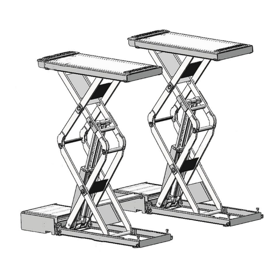
SCISSOR VEHICLE LIFT STD-5335A CHAPTER 2: DESCRIPTION OF THE MACHINE 2.1. INTRODUCTION Scissor-type Lifter adopts the scissor-type mechanical structure; utilize the hydraulic pressure to produce the lifting power. The air pressure controls the lock and loosening of the execution components. The mechanical lock could insure the security and the hydraulic balance valve adjust the lifting flat level. - Page 7 SCISSOR VEHICLE LIFT STD-5335A 2.3. LAYOUT DIMENSION 1500-1940 mm 1375 mm 1375 mm 2.4 TECHNICAL PARAMETER Noise ≤75dB CAPACITY 3500KG Installation place Indoors Max. lifting height 1830mm Weight 762kg Platform initial height 220mm Package size 1530×630×500mm Platform length 1500-1940mm ELECTRONIC MOTOR...
-
Page 12: Chapter 4: Installation
SCISSOR VEHICLE LIFT STD-5335A CHAPTER 4: INSTALLATION Only skilled technicians, appointed by the manufacturer, or by authorized dealers, must be allowed to carry out installation. Serious damage to people and to the lift can be caused if installations are made by unskilled personnel. - Page 16 SCISSOR VEHICLE LIFT STD-5335A For the connection of the pneumatic lines proceed as follow: • Connect the pneumatic lines pre-assembled on the lift to the solenoid air valve in the control unit according to the pneumatic diagram; • Connect the pneumatic system of the lift to the pneumatic supply at site;...
-
Page 17: Chapter 5: Adjustment
SCISSOR VEHICLE LIFT STD-5335A CHAPTER 5: ADJUSTMENT 5.1. START • Make sure all pins and bolts to insure proper mounting • Make sure the electrical system feeding voltage is equal to that specified in the nameplate on the motor • Make sure the electric connections are in compliant with the electrical diagram. - Page 18 SCISSOR VEHICLE LIFT STD-5335A 5.3. CHECKS NO LOAD Carry out two or three complete cycles of lowering and lifting and check: • the safety devices for proper operation • proper oil level in the tank • no leakage and blow-by in hydraulic line and pneumatic line •...
- Page 20 SCISSOR VEHICLE LIFT STD-5335A 6.1. CONTROL Controls for operating the lift are: POWER SWITCH The switch can be set in two positions: • OFF position: the lift electric circuit is not powered; the switch can be padlocked to LOCK prevent the use of the lift.
-
Page 22: Chapter 7: Maintenance
SCISSOR VEHICLE LIFT STD-5335A 7.2. PERIODIC MAINTENANCE Check oil tank level; refill with oil, if needed; Check the circuit for oil Hydraulic circuit leakage. Check seals for proper conditions and replace them, if necessary; Check bolts for proper Every 3 months... -
Page 23: Chapter 8: Troubleshooting
SCISSOR VEHICLE LIFT STD-5335A CHAPTER 8: TROUBLESHOOTING A list of possible troubles and solutions is given below: TROUBLE: POSSIBLE CAUSE: SOLUTION: Connection of power supply Check and correct wire wires is not correct. connection If the motor operates when forcing the contactor down... - Page 24 SCISSOR VEHICLE LIFT STD-5335A When press “Lower” button, The safety pawl are not The “antiknock valve” is the machine is not lowered released form the safety blocked. teeth. The safety pawl is not lifted. The air pressure is not enough, the safety pawl is...
-
Page 25: Chapter 9: Disposal Of Used Oil
SCISSOR VEHICLE LIFT STD-5335A CHAPTER 9: DISPOSAL OF USED OIL Used oil, which is removed from the power unit and the plant during an oil change, must be treated as a polluting product, in accordance with the legal prescriptions of the country in which the lift is installed. -
Page 26: Appendix
SCISSOR VEHICLE LIFT STD-5335A APPENDIX Electrical diagram LINCOS AUTOMOTIVE TOOLS ®... - Page 27 SCISSOR VEHICLE LIFT STD-5335A Foundation installation diagram LINCOS AUTOMOTIVE TOOLS ®...
- Page 28 SCISSOR VEHICLE LIFT STD-5335A Pneumatic diagram Main structure LINCOS AUTOMOTIVE TOOLS ®...
Need help?
Do you have a question about the STD-5335A and is the answer not in the manual?
Questions and answers