
Related Manuals for LINCOS U-B30


Summary of Contents for LINCOS U-B30
- Page 1 USER ’ MANUAL USER ’ MANUAL U-B30/B30Y Low Profile Scissor Lift USER ’ MANUAL USER ’ MANUAL...
-
Page 2: Table Of Contents
USER ’ MANUAL USER ’ MANUAL Contents Contents Packing, Transport and storage Manual Introduction Chapter1. Description of the machine Chapter2. Specifications Chapter3. Safety Chapter4. Installation Chapter5. Adjustment Chapter6. Maintenance and care Chapter7. Failure and resolutions Chapter8. Accessory... - Page 3 G1/4’three-way oil pipe; bridge plate 4 pieces; Pipe line shield: B30: 750MM four units, 630MM two units, 250MM directly knee one unit. B30Y: 750MM four units, 490MM two units, 250MM directly knee one unit. Table 1 Packing dimension picture U-B30(B30Y) Picture 1...
- Page 4 USER ’ MANUAL USER ’ MANUAL PACKING, TRANSPORT AND STORAGE Transport (Picture 2) Packing can be lifted or moved by lift trucks, cranes or bridge cranes. In case of slinging, a second person must always take care of the load, in order to avoid dangerous oscillations.
-
Page 5: Manual Introduction
USER ’ MANUAL USER ’ MANUAL Manual Introduction This manual has been prepared for workshop personnel expert in the use of the lift operator and technicians responsible for routine maintenance fitter. Workers should read the <<Maintenance & Use Manual>> carefully before carrying out any operation with the lift. -
Page 6: Chapter1. Description Of The Machine
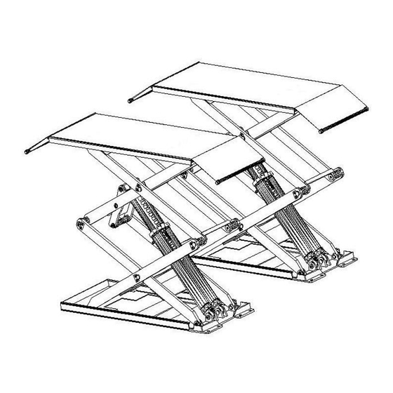
USER ’ MANUAL USER ’ MANUAL Chapter1. Description of the machine Machine Application: small platform profile scissor lift can lift each kind of vehicle whose weight is less than 3000kg, suitable for use in vehicle tests, maintenance, wheel alignment and caring for automobiles, which is particularly suitable for use in the basement or on the floor, without construction and hole. -
Page 7: Chapter2. Specifications
USER ’ MANUAL USER ’ MANUAL Chapter 2.SPECIFICATIONS Main technical parameter Machine type U-B30 U-B30Y Drive Electrical hydraulic Electrical hydraulic Max lift weight 3000kg 3000kg Main machine lift height 1850mm 1850mm Platform initial height 110mm 110mm Platform length 1450mm 1450-2050 mm... - Page 8 USER ’ MANUAL USER ’ MANUAL Chapter 2.SPECIFICATIONS Motor pump Type……………………………Y90L Type…………………………………P4.3 Max power…………………… 2.2kw Model…………………………gear pump Max voltage…AC 400 or 230V ±5% Max electricity………… 400V:5A Max flux…………………………4.3cc/r …………230V:10A Joint type…………joint overfull valve Max Frequency…………………50Hz Continuous working pressure………210bar Poles……………………………… 4 Intermittent working pressure…150~300bar Speed……………………1450rpm/min Inject 20 litters of wearable hydraulic...
- Page 9 USER ’ MANUAL USER ’ MANUAL Chapter 2.SPECIFICATIONS Note: The foundation of the end of the lift platformP1, P2 is the structure of concrete. When the thickness of inside level ground is less than 150mm, the end of P1, P2 should be irrigated the acreage: 2500×2500mm and thickness of concrete≥150mm The basic thickness of concrete and leveling are keys, shouldn’t egregiously expect the ability of level adjustment of machine-self.
-
Page 10: Chapter3. Safety
USER ’ MANUAL USER ’ MANUAL Chapter 3.SAFETY Read this chapter carefully and completely since important information for the safety of the operator or others in case of improper use of the lift is included. In the following text there are clear explanations regarding certain situations of risk or danger that may arise during the operation or maintenance of the lift, the safety device installed and the correct use of such systems, residual risks and operative procedures to use ( general specific precautions to eliminate potential hazards). - Page 11 USER ’ MANUAL USER ’ MANUAL Chapter 3.SAFETY GENERAL PRECAUTIONS The operator and the maintenance fitter are required to observe the prescriptions of safety regulation in force in the country of installation of the lift. Furthermore, the operator and maintenance fitter must: -always work in the stations specified and illustrated in this manual;...
- Page 12 USER ’ MANUAL USER ’ MANUAL Chapter 3.SAFETY GENERAL RISKS FOR LIFTING OR DESCENT : The following safety equipments is used to protect over loading or the possibility of engine failure. In the condition of over loading, the overflow valve will open and directly return oil to the oil tank.
- Page 13 USER ’ MANUAL USER ’ MANUAL Chapter 3.SAFETY RISK OF FALLING (VEHICLE) This hazard may arise in the case of incorrect positioning of the vehicle on the platforms, overweight of the vehicle, or in the case of vehicles of dimensions that are not compatible with the capacity of the lift.
-
Page 14: Chapter4. Installation
USER ’ MANUAL USER ’ MANUAL Chapter 4.INSTALLATION SKILLED AND AUTHORIZED PERSONNEL ONLY SHOULD BE ALLOWED TO PERFORM THESE OPERATIONS, FOLLOW ALL INSTRUCTIONS SHOWN BELOW CAREFULLY, IN ORDER TO PREVENT POSSIBLE DAMAGE TO THE CAR LIFT OR RISK OF INJURY TO PEOPLE. Skilled technicians only, appointed by the same manufacturer or by authorized dealers, are allowed to install the car lift. - Page 15 USER ’ MANUAL USER ’ MANUAL Chapter 4.INSTALLATION -Use fork car or other lifting equipments to lift the platform (Picture14) and make sure that the safety equipment of machine is both turned on and locked. To avoid failure of machine safety equipment, can insert a wood in the middle part of joint-pole.
- Page 16 USER ’ MANUAL USER ’ MANUAL Chapter 4. INSTALLATION COMPRESSED AIR PIPE CONNEVTION: Follow <<air loop diagram >> to connect air loop. Only skilled and authorized person is allowed to perform the operations. -Connect Φ 8 × 6 compressed air supply pipe to the air supply jaws of pneumatic electromagnetic valve inside the control box.
-
Page 17: Chapter5. Adjustment
USER ’ MANUAL USER ’ MANUAL Chapter 5.Adjustment Add oil and check the order of phase. After installing lift as Picture 4 required and connecting hydraulic circuit, electric circuit and air loop, operate it as following: -open the hydraulic oil tank, add 18L of hydraulic oil into the oil tank, the hydraulic oil is provided by the user. - Page 18 USER ’ MANUAL USER ’ MANUAL Chapter 5 Adjustment Picture 20 level adjustment: By using a level bar and the horizontal pipe and adjusting the adjustment screws at tow sides of the base plate. -If platform unevenness is resulted from basic unevenness, use iron block to fill up the low place.
- Page 19 USER ’ MANUAL USER ’ MANUAL Chapter 5.Adjustment When beginning load of machine test, no person or other things are allowed to stand or be put near the two sides and beneath the machine. Test vehicle whose weight doesn’t exceed maximum lift weight. Check whether the oil line and the air line are leakage.
- Page 20 USER ’ MANUAL USER ’ MANUAL Chapter 5.Adjustment Oil make-up “adjust” operation ( normal service period): after completion of machine installation and adjustment in the application process, the right platform is lower than the left one because of air in the oil cylinder not being excluded completely normal looses or leakage of the hydraulic oil.
-
Page 21: Chapter6. Maintenance And Care
USER ’ MANUAL USER ’ MANUAL Chapter 6.Maintenance and care Skilled personnel only is allowed to perform the operations. -all bearings and hinges on this machine must be lubricated once a week by using an oiler. -the safety gear, the upper and lower sliding blocks and other movable parts must be lubricated once o month. -
Page 22: Chapter7. Failure And Resolutions
USER ’ MANUAL USER ’ MANUAL Chapter 7.Failure and resolutions Skilled personnel only is allowed to perform the operations. Failure Phenomena and Resolutions Cause and Phenomena Resolutions Failure Phenomena ① Connection of power Check and correct wire connection supply wires is not correct. If the motor operates when forcing the contactor ②... - Page 23 USER ’ MANUAL USER ’ MANUAL main platform and sub cylinder. overflowing valve main platform and main cylinder descent valve sub platform and sub cylinder gear pump sub platform and main cylinder throttling valve stop valve pump motor one-way valve filter 13.
- Page 24 USER ’ MANUAL USER ’ MANUAL A: descent valve; B: manual descent knob; C: one-way valve; D: motor; E: overflowing valve ; F: Plug; G work stop valve ; H、I. added stop valve; Hose connection diagram...
- Page 25 USER ’ MANUAL USER ’ MANUAL...
Need help?
Do you have a question about the U-B30 and is the answer not in the manual?
Questions and answers