
Related Manuals for Echo BEAR CAT CH5653


Summary of Contents for Echo BEAR CAT CH5653
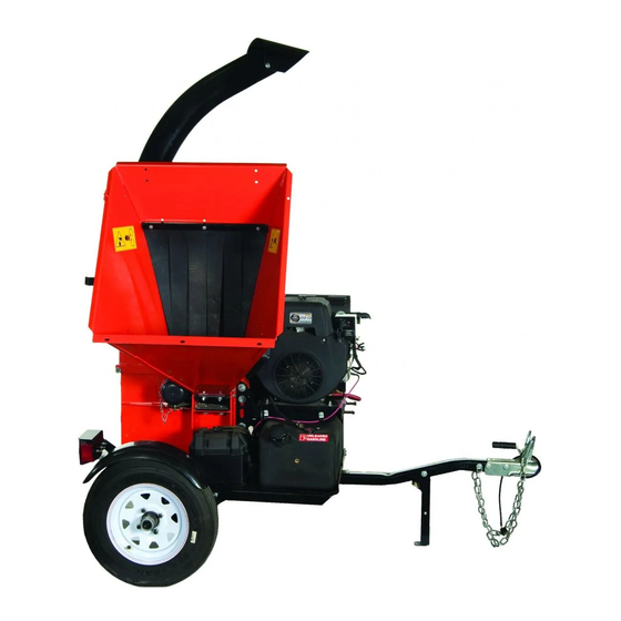
- Page 1 www.bearcatproducts.com 5 INCH CHIPPER CH5653 – 653cc SUBARU PN: 31602-00 Rev. 010113 Companion to 31603-00 Range: 5VJAA0000DW000001 - 5VJAA0215JW005776...
- Page 2 Please read and understand this manual before operating your machine. If you have any questions or comments about this manual, please call us toll-free at 1.888.625.4520. If you have any questions or problems with your machine, please call or write your local authorized ECHO Bear Cat Dealer.
- Page 3 Crary Industries, Inc. In the event of a failure, return the product, at your cost, along with proof of purchase to the selling ECHO Bear Cat dealer. Crary Industries, Inc. will, at its option, repair or replace any parts found to be defective in material or workmanship.
-
Page 4: Table Of Contents
TABLE OF CONTENTS SAFETY ..............1 SERVICE & MAINTENANCE ......12 1.1 SAFETY ALERT SYMBOL ........1 5.1 MAINTENANCE SCHEDULE ......... 12 1.2 FIRE HAZARD INFORMATION ........ 1 5.2 ROTOR LOCK ............13 1.3 BEFORE OPERATING ..........1 5.3 RAISE/LOWER ACCESS COVER ......13 1.4 OPERATION SAFETY .......... -
Page 5: Safety
SAFETY Section The engine on your power equipment, like most outdoor 1.1 SAFETY ALERT SYMBOL power equipment, is an internal combustion engine that burns gasoline or diesel fuel (hydrocarbons). If operating your power equipment in affected areas, it must be equipped with a spark arrestor in continuous effective working order. -
Page 6: Operation Safety
SAFETY 7. Do not operate this equipment in 4. Do not climb on machine when operating. Keep proper the vicinity of bystanders. Keep balance and footing at all times. the area of operation clear of 5. Check cutting chamber to verify it is empty before all persons, particularly small starting the machine. -
Page 7: Battery Safety
SAFETY 1.5 BATTERY SAFETY 1.6 MAINTENANCE/STORAGE SAFETY Improper use and care of the battery on electric start 1. Before inspecting, servicing, storing, or changing models can result in serious personal injury or property an accessory, shut off the machine and make sure damage. -
Page 8: Safety Decals
SAFETY 1.8 SAFETY DECALS See Section 1.9 for decal locations. Familiarize yourself with all of the safety and operating decals on the machine and the associated hazards. See the engine owner's manual or contact the engine manufacturer for engine safety instructions and decals. -
Page 9: Safety Decal Locations
SAFETY PN 32327-00 ENG. & FR. PN 32330-00 ENG. & FR. (32339-00 ESP. & PORT.) (32342-00 ESP. & PORT.) PN 32328-00 ENG. & FR. PN 32332-00 ENG. & FR. (32340-00 ESP. & PORT.) (32341-00 ESP. & PORT.) *Decals 10-13 not for CE compliant machines. 1.9 SAFETY DECAL LOCATIONS The numbers below correspond to the decals in Section 1.8. -
Page 10: Assembly
ASSEMBLY Section 2.2 ATTACH TRAILER HITCH WARNING 1. First, attach the hitch pole assembly (8) to the hitch If any bolts or nuts are dropped in the machine, be sure channel in the trailer deck bottom with three 3/8 x 3" to remove them before starting the machine. -
Page 11: Attach Chipper Chute
ASSEMBLY 2.3 ATTACH CHIPPER CHUTE 1. Use a support or hoist to hold the chipper chute in place on the chipper frame. 2. Mount the chute to the chipper housing using six 3/8 x 1" carriage bolts and nylock nuts. Figure 2.6, Attach Discharge Tube Figure 2.4, Attach Chipper Chute NOTE... -
Page 12: Add Oil To Engine
ASSEMBLY 2.5 ADD OIL TO ENGINE 2.7 FILL THE FUEL TANK Check the oil level and, if needed, fill the engine crankcase WARNING with the type and amount of oil specified in the engine owner’s manual. Gasoline and diesel fuels are highly flammable their vapors... -
Page 13: Features & Controls
FEATURES & CONTROLS Section Understanding how your machine works will help you achieve the best results when using your chipper. The following descriptions define the features and controls of your machine. REFER TO ENGINE OWNER'S MANUAL FOR FURTHER ENGINE OPERATING INSTRUCTIONS. 1. -
Page 14: Operation
OPERATION Section As with any other piece of outdoor equipment, getting the 5. Turn the key to the START position. Release the key feel for how your machine operates and getting to know as soon as the engine starts. Do not crank engine for the best techniques for particular jobs are important to more than 10 seconds. -
Page 15: Towing
OPERATION 3. Exclude pieces of metal, rocks, bottles, cans, and CAUTION other foreign objects when feeding material into the machine. ● Obtain and wear safety glasses at all times when 4. Feed brush from the side of the chipper chute, operating the machine. -
Page 16: Service & Maintenance
SERVICE & MAINTENANCE Section 5.1 MAINTENANCE SCHEDULE The items listed in this service and maintenance schedule are to be checked, and if necessary, corrective action taken. This schedule is designed for units operating under normal conditions. If the unit is operating in adverse or severe conditions, it may be necessary for the items to be checked and serviced more frequently. -
Page 17: Rotor Lock
SERVICE & MAINTENANCE WARNING BEFORE INSPECTING OR SERVICING ANY PART OF THIS MACHINE, SHUT OFF POWER SOURCE AND MAKE SURE ALL MOVING PARTS HAVE COME TO A COMPLETE STOP. 5.2 ROTOR LOCK 5.4 CHIPPER BLADES MAINTENANCE The chipper blades will eventually become dull, making WARNING chipping difficult and adding extra strain on the machine. -
Page 18: Removing The Blades
SERVICE & MAINTENANCE WARNING BEFORE INSPECTING OR SERVICING ANY PART OF THIS MACHINE, SHUT OFF POWER SOURCE AND MAKE SURE ALL MOVING PARTS HAVE COME TO A COMPLETE STOP. 5. Remove an equal amount off each blade to maintain 5.5 REMOVING THE BLADES rotor balance. -
Page 19: Trailer Maintenance Tips
SERVICE & MAINTENANCE WARNING BEFORE INSPECTING OR SERVICING ANY PART OF THIS MACHINE, SHUT OFF POWER SOURCE AND MAKE SURE ALL MOVING PARTS HAVE COME TO A COMPLETE STOP. To adjust the chipping anvil: 5.10 CLEARING A PLUGGED ROTOR 1. Lift rotor access cover and expose rotor. Loosen the two 1/2"... -
Page 20: Replacing Rotor Bearings
SERVICE & MAINTENANCE WARNING BEFORE INSPECTING OR SERVICING ANY PART OF THIS MACHINE, SHUT OFF POWER SOURCE AND MAKE SURE ALL MOVING PARTS HAVE COME TO A COMPLETE STOP. 6. Then remove the drive belt from pulleys. 5.12 REPLACING ROTOR BEARINGS 7. -
Page 21: Change Oil
SERVICE & MAINTENANCE WARNING BEFORE INSPECTING OR SERVICING ANY PART OF THIS MACHINE, SHUT OFF POWER SOURCE AND MAKE SURE ALL MOVING PARTS HAVE COME TO A COMPLETE STOP. 16. Install the spacer on the shaft. 5.14 LUBRICATION 17. Slide the sheave onto the shaft and then install the bushing and slide it all the way up to the spacer. -
Page 22: Troubleshooting
Before performing any of the corrections in this troubleshooting chart, refer to the appropriate information contained in this manual for the correct safety precautions and operating or maintenance procedures. Contact your dealer or ECHO Bear Cat for service problems with the machine. - Page 23 TROUBLESHOOTING PROBLEM POSSIBLE CAUSES REMEDY Improper belt installation, belt not under belt Install belt properly, install belt under belt guide guide Cannot engage belt Adjust belt tension, Replace belt or belt Improper belt tension tension spring if needed Drive belt too loose or broken Replace belt or spring Use branch or similar object to clear Rotor will not turn...
-
Page 24: Specifications
SPECIFICATIONS Section DESCRIPTION ENGLISH METRIC Overall size 80 x 57 x 95" 203 x 145 x 241 cm Overall weight 950 lbs. 431 kg Max chipper capacity 5" dia. 12.7 cm dia. Chipper blades 4 reversible heat treated Chipping anvil 5.63"... -
Page 25: Bolt Torque
SPECIFICATIONS 7.1 BOLT TORQUE The tables below are for reference purposes only and their use by anyone is entirely voluntary, unless otherwise noted. Reliance on their content for any purpose is at the sole risk of that person and any loss or damage resulting from the use of this information is the responsibility of that person. -
Page 26: Options
OPTIONS Section PART NUMBER DESCRIPTION 72493 KIT, CHIPPER BLADE 31605-00 METER, TACH/HOUR Chipper Blade Kit, 72493 Tach/Hour Meter Kit, 31605-00 5 INCH CHIPPER... - Page 27 ECHO BEAR CAT www.bearcatproducts.com 237 NW 12th Street, West Fargo, ND 58078-0849 Phone: 701.282.5520 • Toll Free: 888.645.4520 • Fax: 701.282.9522 E-mail: service@bearcatproducts.com • sales@bearcatproducts.com...
Need help?
Do you have a question about the BEAR CAT CH5653 and is the answer not in the manual?
Questions and answers