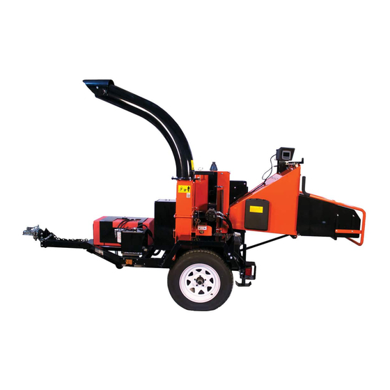
Echo Bear Cat CH922DH Owner's Manual
2.2 l diesel kubota 9 inch chipper
Hide thumbs
Also See for Bear Cat CH922DH:
- Specifications (2 pages) ,
- Specification sheet (1 page) ,
- Specification sheet (1 page)

Related Manuals for Echo Bear Cat CH922DH


Summary of Contents for Echo Bear Cat CH922DH
- Page 1 9 INCH CHIPPER CH922DH – 2.2 L Diesel Kubota ® PN: 72693-00 Rev. 031119 bearcatproducts.com Companion to 72694-00 Range: 5VJAA0415KW006182 - Current...
- Page 2 Please read and understand this manual before operating your machine. If you have any questions or comments about this manual, please call us toll-free at 888.625.4520. If you have any questions or problems with your machine, please call or write your local authorized ECHO Bear Cat Dealer.
- Page 3 Repair or attempted repair by anyone other than an authorized ECHO Bear Cat dealer as well as subsequent failure or damage that may occur as a result of that work will not be paid under this warranty.
-
Page 4: Table Of Contents
TABLE OF CONTENTS SAFETY ..............1 SERVICE & MAINTENANCE ......20 1.1 SAFETY ALERT SYMBOL ........1 5.1 MAINTENANCE SCHEDULE ......... 20 1.2 FIRE HAZARD INFORMATION ........ 1 5.2 ROTOR LOCK ............21 1.3 BEFORE OPERATING ..........1 5.3 RAISE/LOWER ACCESS COVER ......21 1.4 OPERATION SAFETY .......... -
Page 5: Safety
SAFETY Section The engine on your power equipment, like most outdoor 1.1 SAFETY ALERT SYMBOL power equipment, is an internal combustion engine that burns gasoline or diesel fuel (hydrocarbons). If operating your power equipment in affected areas, it must be equipped with a spark arrestor in continuous effective working order. -
Page 6: Operation Safety
SAFETY 7. Do not operate this equipment in the vicinity of 6. The rotor will continue to rotate after being disengaged. bystanders. Keep the area of operation clear of all Shut off the machine and make sure all moving parts persons, particularly small children. -
Page 7: Battery Safety
SAFETY 6. Stand to side of feed chute when feeding material 1.7 MAINTENANCE/STORAGE SAFETY and release material quickly. 7. When inspecting or servicing the feed roller, secure 1. Before inspecting, servicing, storing, or changing the feed roller in the raised position using the lock pin, an accessory, shut off the machine and make sure if applicable. -
Page 8: Safety Decals
SAFETY 1.9 SAFETY DECALS See Section 1.10 for decal locations. Familiarize yourself with all of the safety and operating decals on the machine and the associated hazards. See the engine owner’s manual or contact the engine manufacturer for engine safety instructions and decals. -
Page 9: Safety Decal Locations
SAFETY PN 32327-00 ENG. & FR. PN 32330-00 ENG. & FR. (32339-00 ESP. & PORT.) (32342-00 ESP. & PORT.) PN 32328-00 ENG. & FR. PN 32332-00 ENG. & FR. (32340-00 ESP. & PORT.) (32341-00 ESP. & PORT.) *Decals 12-15 not for CE compliant machines. 1.10 SAFETY DECAL LOCATIONS The numbers below correspond to the decals in Section 1.9. -
Page 10: Assembly
ASSEMBLY Section WARNING If any bolts or nuts are dropped in the machine, be sure to remove them before starting the machine. 2.1 ATTACH TRAILER WHEELS 1. Remove the chipper from its shipping crate. Place the unit on a level surface before attempting to assemble. 2. -
Page 11: Attach Chute And Support
ASSEMBLY 2.4 ATTACH CHUTE AND SUPPORT WARNING NOTE In tropical regions, areas of high humidity or rainfall Do not operate this unit without the chipper chute amounts, dielectric grease may be added to wire correctly installed. Rotating cutting blades can cause harness connectors to provide corrosion resistance. -
Page 12: Attach Digital Display Controller Mount Assembly
ASSEMBLY 2.5 ATTACH DIGITAL DISPLAY CONTROLLER MOUNT ASSEMBLY 1. Remove the bolts (1) and nuts (2) attaching the digital display controller mount assembly (3) to the inside of the chute. 2. Attach mount assembly to the outside of the chute as shown. -
Page 13: Attach Discharge Tube
ASSEMBLY 2.7 ATTACH DISCHARGE TUBE 1. Attach one clamping ring (1) and one spacer ring (2) NOTE to discharge tube base (3) using three 3/8" × 1-1/4" bolts (4) and nylock nuts (5). Tighten leaving 1/16" Keep nuts as tight as possible while allowing the gap to assist in mounting to flange. -
Page 14: Add Oil To Engine
ASSEMBLY To install the battery: 2.8 ADD OIL TO ENGINE 1. Open the battery box (11-1/8" × 7-3/4" × 10-1/8") and insert battery into the battery box. Check the oil level and, if needed, fill the engine crankcase with the type and amount of oil specified in the engine 2. -
Page 15: Features & Controls
FEATURES & CONTROLS Section Understanding how your machine works will help you achieve the best results when using your chipper. The following descriptions define the features and controls of your machine. REFER TO ENGINE OWNER’S MANUAL FOR FURTHER ENGINE OPERATING INSTRUCTIONS. 9 INCH CHIPPER... - Page 16 FEATURES & CONTROLS 1. CHUTE EXTENSION TRAY 12. MANUAL CONTAINER The feed chute has an extension tray that folds down. Conveniently holds your manuals. Raise the extension tray to an upright position and 13. REAR STABILIZER secure with latch before towing the machine. Prevents the chipper from tipping when disconnected 2.
-
Page 17: Operation
OPERATION Section As with any other piece of outdoor equipment, getting the 5. Press engine start button until engine starts or a feel for how your machine operates and getting to know maximum of 10 seconds (to prevent burning out the the best techniques for particular jobs are important to starter). - Page 18 OPERATION 3. If the chipper engine stalls while engaging the belt, depress the belt engagement pedal again to disengage belt, restart engine, SLIGHTLY increase throttle and attempt engagement again. 4. Once the belt is engaged, continue to SLOWLY turn the throttle knob counterclockwise to increase throttle to 100% or full throttle.
-
Page 19: Chipper Operation Guidelines
OPERATION 7. Limbs fed in to the chipper chute must be 9" 4.3 CHIPPER OPERATION GUIDELINES (22.9 cm) in diameter or less. Trim side branches that cannot be bent enough to feed into the chipper chute. Hold small diameter branches together in a WARNING bundle and feed in simultaneously. -
Page 20: Slowing And Stopping The Chipper Rotor And Engine
OPERATION 4.6 CHIPPER FEED CONTROLLER 4.4 SLOWING AND STOPPING THE CHIPPER ROTOR AND ENGINE This machine is equipped with a Digital Display Controller (DDC). The DDC monitors the chipper rotor RPM and NEVER disengage the belt as part of the stopping or regulates the feed roller. -
Page 21: Using The Digital Display Controller
Enter key. The user should 4.7.1 MAIN MENU navigate to the Hours/Service Reminders screen for After turning the key to the ON position, the ECHO Bear more information on the service required. The Hours/ logo will be displayed followed by the screen shown Service Reminders are described in Section 4.7.3. - Page 22 OPERATION Bar safety system has been activated. To re-engage the In the upper left hand corner of the screen is a reminder that the feed roller speed can be adjusted. The adjustment feed roller safety system after the Knee Bar safety occurs at the control valve, the location of which varies by system has been activated, the operator must press model.
-
Page 23: Towing
OPERATION After a service operation has been performed, that Service Indicator Reminder will need to be reset. Using the Navigation Button, move the cursor to the appropriate service reminder, then press and hold the Reset button for three seconds. 4.7.4 LANGUAGE The language used to display messages on the controller can be changed to one of four options on the Language selection screen. -
Page 24: Service & Maintenance
SERVICE & MAINTENANCE Section 5.1 MAINTENANCE SCHEDULE The items listed in this service and maintenance schedule are to be checked, and if necessary, corrective action taken. This schedule is designed for units operating under normal conditions. If the unit is operating in adverse or severe conditions, it may be necessary for the items to be checked and serviced more frequently. -
Page 25: Rotor Lock
SERVICE & MAINTENANCE WARNING BEFORE INSPECTING OR SERVICING ANY PART OF THIS MACHINE, SHUT OFF POWER SOURCE, DISENGAGE THE HYDRAULICS, OPEN SHIELD AND MAKE SURE ALL MOVING PARTS HAVE COME TO A COMPLETE STOP. 5.2 ROTOR LOCK 5.4 CHIPPER BLADES MAINTENANCE The chipper blades will eventually become dull, making WARNING chipping difficult and adding extra strain on the machine. -
Page 26: Removing The Blades
SERVICE & MAINTENANCE WARNING BEFORE INSPECTING OR SERVICING ANY PART OF THIS MACHINE, SHUT OFF POWER SOURCE, DISENGAGE THE HYDRAULICS, OPEN SHIELD AND MAKE SURE ALL MOVING PARTS HAVE COME TO A COMPLETE STOP. 3. Be careful when grinding so that the blade does 5.5 REMOVING THE BLADES not become overheated and change color. -
Page 27: Setting Chipper Blade Clearance
SERVICE & MAINTENANCE WARNING BEFORE INSPECTING OR SERVICING ANY PART OF THIS MACHINE, SHUT OFF POWER SOURCE, DISENGAGE THE HYDRAULICS, OPEN SHIELD AND MAKE SURE ALL MOVING PARTS HAVE COME TO A COMPLETE STOP. ROTOR 5.8 SETTING CHIPPER BLADE CLEARANCE CHIPPER BLADE The chipping blades should clear the chipper block ANVIL... -
Page 28: Drive Belts
SERVICE & MAINTENANCE WARNING BEFORE INSPECTING OR SERVICING ANY PART OF THIS MACHINE, SHUT OFF POWER SOURCE, DISENGAGE THE HYDRAULICS, OPEN SHIELD AND MAKE SURE ALL MOVING PARTS HAVE COME TO A COMPLETE STOP. 2. Open access cover (see Section 5.3). 2. -
Page 29: Hydraulic Feed Maintenance
SERVICE & MAINTENANCE WARNING BEFORE INSPECTING OR SERVICING ANY PART OF THIS MACHINE, SHUT OFF POWER SOURCE, DISENGAGE THE HYDRAULICS, OPEN SHIELD AND MAKE SURE ALL MOVING PARTS HAVE COME TO A COMPLETE STOP. 5. Loosen bolts on hydraulic pump and remove hydraulic 12. -
Page 30: Change Hydraulic Fluid Filter
SERVICE & MAINTENANCE WARNING BEFORE INSPECTING OR SERVICING ANY PART OF THIS MACHINE, SHUT OFF POWER SOURCE, DISENGAGE THE HYDRAULICS, OPEN SHIELD AND MAKE SURE ALL MOVING PARTS HAVE COME TO A COMPLETE STOP. 1. Clean all system components (reservoir, fittings, etc.). 5.15 CHANGE OIL 2. -
Page 31: Lubrication
SERVICE & MAINTENANCE WARNING BEFORE INSPECTING OR SERVICING ANY PART OF THIS MACHINE, SHUT OFF POWER SOURCE, DISENGAGE THE HYDRAULICS, OPEN SHIELD AND MAKE SURE ALL MOVING PARTS HAVE COME TO A COMPLETE STOP. 5.17 LUBRICATION WARNING NOTE Do not over grease bearings. Overfilling can lead to Polyurea lithium-based greases... -
Page 32: Troubleshooting
TROUBLESHOOTING Section 6.1 FLASH CODES FOR THE DIGITAL DISPLAY CONTROLLER FREQUENCY CAUSE ACTION TO TAKE GREEN Chipper has reached required RPM Solid Machine ready for chipping and forward feed is available 1/2 second on, Chipper has not reached chipping RPM Slowly increase RPM 1/2 second off upon initial startup... -
Page 33: Troubleshooting Guide
6.2 TROUBLESHOOTING GUIDE Before performing any of the corrections in this troubleshooting chart, refer to the appropriate information contained in this manual for the correct safety precautions and operating or maintenance procedures. Contact your dealer or ECHO Bear Cat for service problems with the machine. - Page 34 TROUBLESHOOTING PROBLEM POSSIBLE CAUSES REMEDY Dull chipper blades Flip, sharpen, or replace Hard to feed chipper, Use branch or similar object to clear Obstructed discharge requires excessive discharge tube power to chip Set blade/anvil clearance to recommended Improper blade clearance distance Dull chipper blades Flip, sharpen, or replace...
-
Page 35: Specifications
SPECIFICATIONS Section DESCRIPTION ENGLISH METRIC Overall size (L × W × H) 127" × 79" × 100" 323 cm × 201 cm × 254 cm Overall weight 2725 lbs. 1236 kg Max chipper capacity 9" diameter 22.9 cm diameter Chipper blades 4 reversible (5"... -
Page 36: Bolt Torque
SPECIFICATIONS 7.1 BOLT TORQUE The tables below are for reference purposes only and their use by anyone is entirely voluntary, unless otherwise noted. Reliance on their content for any purpose is at the sole risk of that person and any loss or damage resulting from the use of this information is the responsibility of that person. -
Page 37: Temperature Operating Window
SPECIFICATIONS 7.2 TEMPERATURE OPERATING WINDOW For the nearest Mobil lubricant supplier or technical information, including lubricant information for severe arctic operating conditions, call 800-662-4525. 9 INCH CHIPPER... -
Page 38: Options
OPTIONS Section PART NUMBER DESCRIPTION 14519-00 COUPLER, 2-5/16 20,000 LB 14900-00 HITCH, PINTLE RING 20,000 LB 33900-00 KEY, DSE 71072-00 KIT, CHIPPER ELECTRIC BRAKES 71725-00 KIT, LOW PROFILE DISCHARGE CHUTE 71731-00 KIT, FINE-CHIP ROTOR 71921 KIT, HOUR METER 76293-00 KIT, CHIPPER BLADE (1/2 INCH) 76721-00 KIT, BATTERY DISCONNECT Pintle Hitch, 14900-00... - Page 39 ECHO Bear Cat ® bearcatproducts.com 237 NW 12th Street, West Fargo, ND 58078-0849 Phone: 701.282.5520 • Toll Free: 888.625.4520 • Fax: 701.282.9522 E-mail: service@bearcatproducts.com • sales@bearcatproducts.com...
Need help?
Do you have a question about the Bear Cat CH922DH and is the answer not in the manual?
Questions and answers