
Related Manuals for Echo CH5540


Summary of Contents for Echo CH5540
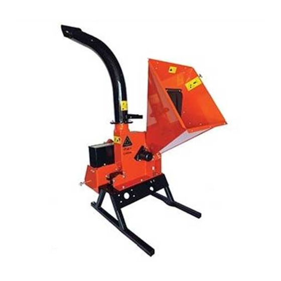
- Page 1 5 InCH pTo CHIpper CH5540 - PTO Manual PN 31588-00 Rev. 010111 Companion to PN 31589-00 SN Range: B00001 - C08854...
- Page 2 Please read and understand this manual before operating your machine. If you have any questions or comments about this manual, please call us toll-free at 1-800-247-7335. If you have any questions or problems with your machine, please call or write your local authorized ECHO Bear Cat Dealer.
- Page 3 lImITeD warranTY This warranty applies to all Ag and Outdoor Power Equipment manufactured by Crary Industries. Crary Industries warrants to the original owner each new Crary Industries product to be free from defects in material and workmanship, under normal use and service. The warranty shall extend 1 year from date of delivery for income producing (commercial) applications and 2 years from date of delivery for non-income producing (consumer) use of the product.
-
Page 4: Table Of Contents
TaBle oF ConTenTs DesCrIpTIon paGe saFeTY ........................ 1 1.1 SAFETy AlERT SyMBOl ..................1 1.2 BEFORE OPERATINg ...................1 1.3 OPERATION SAFETy ...................2 1.4 PTO SAFETy ......................2 1.5 MAINTENANCE/STORAgE SAFETy ..............2 1.6 SAFETy DECAl lOCATIONS ................3 1.7 SAFETy DECAlS ....................4 assemBlY ......................5 2.1 ATTACH CHIPPER CHuTE ...................5 2.2 ATTACH DISCHARgE TuBE .................6 2.3 CONNECT PTO DRIVElINE .................7... -
Page 5: Safety
saFeTY Section 1.2 BeFore operaTInG 1.1 saFeTY alerT sYmBol 1. Read and understand this owner’s manual. Be completely familiar with the controls and the proper use of this equipment. 2. Familiarize yourself with all of the safety and operating decals on this equipment and on any of its attachments or accessories. -
Page 6: Operation Safety
SAFETY 1.3 operaTIon saFeTY 1.4 pTo saFeTY 1. Read and follow instructions on PTO safety decals. 1. Always stand clear of discharge area when operating this machine. Keep face and body away from feed and 2. Stay alert and pay attention when PTO is operating. discharge openings. -
Page 7: Safety Decal Locations
SAFETY 1.6 saFeTY DeCal loCaTIons The numbers below correspond to the decals in Section 1.7. Familiarize yourself with all of the safety and operational decals on the machine and the associated hazards. See the engine owner’s manual or contact the engine manufacturer for engine safety instructions and decals. -
Page 8: Safety Decals
SAFETY 1.7 saFeTY DeCals See Section 1.6 for decal locations. Familiarize yourself with all of the safety and operating decals on the machine and the associated hazards. See the engine owner’s manual or contact the engine manufacturer for engine safety instructions and decals. -
Page 9: Assembly
assemBlY Section 2.1 aTTaCH CHIpper CHuTe 1. use a support or hoist to hold the chipper chute in place warnInG on the chipper frame. Do not operate this unit without the chipper chute 2. Mount the chute to the chipper housing using six 3/8" correctly installed. -
Page 10: Attach Discharge Tube
ASSEMBLY 2.2 aTTaCH DIsCHarGe TuBe 1. Attach one clamping ring(1) and one spacer ring(2) to noTe discharge tube base(3) using three 3/8 x 1 1/4" bolts(4) and nylock nuts(5). Tighten leaving 1/16" gap to assist Keep nuts as tight as possible while allowing the in mounting to flange. -
Page 11: Connect Pto Driveline
ASSEMBLY 2.3 ConneCT pTo DrIvelIne The driveline supplied with this machine may need to be ImporTanT cut to a shorter length for proper operation with the tractor being used. To determine if driveline will need to be cut, • The tractor must have a standard 540 rpm pTo shaft. follow steps below or consult attached driveline manual. -
Page 12: Features & Controls
FeaTures & ConTrols Section 1. Three point hitch connection: Mounts chipper to 4. Chipper chute: Feed materials to be chipped through tractor three point hitch. the chipper chute. 2. pTo driveline: Connects chipper to tractor PTO 5. leg stands: Never move machine unless the 3 point shaft. -
Page 13: Operation
operaTIon Section As with any other piece of outdoor equipment, getting the ImporTanT feel for how your machine operates and getting to know the best techniques for particular jobs are important to This chipper is designed to be used with a tractor overall good performance. -
Page 14: Operating The Chipper
OPERATION 7. If the chipper jams, remove the branch and rotate it 4.3 operaTInG THe CHIpper before reinserting it into the chute. Alternately insert and retract the limb or insert continuously at a rate that warnInG will not kill the engine. Read and follow all safety instructions in this manual. -
Page 15: Service & Maintenance
servICe & maInTenanCe Section 5.1 maInTenanCe sCHeDule warnInG The items listed in this service and maintenance schedule To prevent personal injury or property damage: shut are to be checked, and if necessary, corrective action taken. off engine and make sure that all moving parts have This schedule is designed for units operating under normal come to a complete stop before, servicing, adjusting or conditions. -
Page 16: Chipper Blade Maintenance
SERVICE & MAINTENANCE WARNING BEFORE INSPECTING OR SERVICING ANY PART OF THIS MACHINE, SHUT OFF POWER SOURCE AND MAKE SURE ALL MOVING PARTS HAVE COME TO A COMPLETE STOP. 5.2 CHIpper BlaDe maInTenanCe 5.3 removInG THe BlaDes To remove the chipper blades: warnInG 1. -
Page 17: Setting The Blade Clearance
SERVICE & MAINTENANCE WARNING BEFORE INSPECTING OR SERVICING ANY PART OF THIS MACHINE, SHUT OFF POWER SOURCE AND MAKE SURE ALL MOVING PARTS HAVE COME TO A COMPLETE STOP. 4. Tighten bolts on chipping anvil to 75 ft-lbs. Make 4. use short grinding times and cool with water or some sure all blades clear the anvil by 1/16"... -
Page 18: Replacing Rotor Bearings
11. Replace belt guard and resume operation. 12. Start tractor engine and engage PTO drive clutch (see tractor owner's manual). Increase engine speed to Figure. 5.6. Grease zerks on CH5540 rated PTO RPM Position. Test unit; readjust pulleys if needed. -
Page 19: Pto Lubrication
8 hours of operation. Figure 5.8. PTO lubrication Figure. 5.7. Grease zerks on CH5540 ImporTanT Polyurea and lithium-based greases are not compatible. Mixing the two grease types may lead to premature failure. -
Page 20: Troubleshooting
TrouBlesHooTInG Section Before performing any of the corrections in this troubleshooting chart, refer to the appropriate information contained in this manual for the correct safety precautions and operating or maintenance procedures. Contact your dealer or the factory for service problems with the machine. proBlem possIBle Causes remeDY... -
Page 21: Specifications
Section CH5540 DesCrIpTIon english metric OVERAll SIZE 48" x 45" x 87" 122.0 x 114.3 x 221.0 cm OVERAll WEIgHT 600 lbs. 272.7 kg MAX CHIPPER CAPACITy 5" 12.7 cm CHIPPER BlADES 4 Reversible Tool Steel 4 Reversible Tool Steel CHIPPINg ANVIl 5.63"... -
Page 22: Bolt Torque
BolT TorQue The tables below are for reference purposes only and their use by anyone is entirely voluntary, unless otherwise noted. Reliance on their content for any purpose is at the sole risk of that person and any loss or damage resulting from the use of this information is the responsibility of that person. -
Page 23: Options
opTIons Section part # DeCsCrIpTIon 72493 KIT, CHIPPER BlADES 4 INCH CHIPPER...
Need help?
Do you have a question about the CH5540 and is the answer not in the manual?
Questions and answers