Advertisement
Quick Links
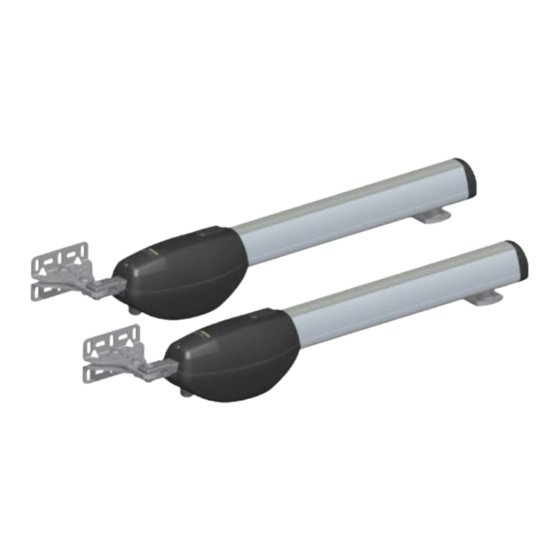
EDGE1 is the range of 36V DC digital controllers installed with the swing gates applications.
1. Typical installation
2
A
EDGE1 - Motors connection
1
Photocell - Receiver
2
Photocell - Transmitter
3
Flashing lamp unit
4
Antenna
5
Selector / Keypad
(purely for information)
4
3
5
1
A
3x2,5 mm
double insulated cable (max 10 m) - 3x4 mm
2
5x0,5 mm
double insulated cable (max 20 m)
2
3x0,5 mm
double insulated cable (max 20 m)
2
2x1 mm
double insulated cable (max 10 m)
2
RG58 or KX6 50 Ohm cable for external use (max 10 m)
3x0,5 mm
cable (max 20 m)
2
Quick Start EDGE1
1
Via S. Botticelli 8 • 31021 Bonisiolo di Mogliano Veneto (TV) • ITALIA
P.IVA 01612340263 • Tel. +39 041.5937023 • Fax. +39 041.5937024
info@rogertechnology.com • www.rogertechnology.com
Rev02 03/04/2020
2
A
(max 30 m)
2
ROGER TECHNOLOGY
EN
Advertisement

Related Manuals for Roger Technology EDGE1


Summary of Contents for Roger Technology EDGE1
- Page 1 Quick Start EDGE1 Rev02 03/04/2020 EDGE1 is the range of 36V DC digital controllers installed with the swing gates applications. 1. Typical installation (purely for information) EDGE1 - Motors connection 3x2,5 mm double insulated cable (max 10 m) - 3x4 mm...
-
Page 2: Electrical Connections
2. Electrical connections PRIMARY CS/STD SECONDARY Blu/Blue Blu/Blue Blu/Blue Blu/Blue Nero/Black Nero/Black Nero/Black Nero/Black POWER SUPPLY 230 Vac / 115 SEC2 SEC1 PROG TEST TRANSFORMER F4ES-F4S BATTERIES Series 1 2 3 2 3 4 5 COS1 COS2 2 x 12V 4,5Ah FIFTHY/24 +24V +LAM... - Page 3 4. Before starting ... a) Select the automation system model installed with the parameter A1. BE20/200/HS SMARTY 5R5 * BR20 Series SMARTY 4HS BH23/282 BH23/252/HS BR21 Series BR21/351/HS SMARTY 5 BE20/400 SMARTY 7 MONOS4 SMARTY 7R * BR20/400/R * the parameter 71 01 must be set and SMARTY/EMA installed for all applications with the SMARTY REVERSIBLE motor. 1 MOTOR 2 MOTORS b) Select the number of motors installed with the parameter 70.
-
Page 4: Setting Basic Parameters
5. Acquisition procedure 1. Press and hold PROG for 4 seconds. 2. APP- appears on the display. 3. Press PROG. 4. AUTO appears on the display. 5. MOTOR 1 starts opening at low speed. 6. After the delay time set with parameter 25, MOTOR 2 starts an opening manoeuvre. 7. - Page 5 9. Photocells grounding connection Grounding connection negative terminal (COM) photocells series F4ES/F4S or other than Roger Technology In case of malfunction, or failure to intervene in case of dimming, or continuous detection, or abnormal behaviour of the automation (gate, overhead door, barrier, etc.), it is advisable to connect the negative terminal (COM) of the photocells to the grounding of the system.
Need help?
Do you have a question about the EDGE1 and is the answer not in the manual?
Questions and answers