Table of Contents
Advertisement
Quick Links
Advertisement
Table of Contents

Related Manuals for inogeni CAM230


Summary of Contents for inogeni CAM230
- Page 1 INOGENI CAM230 User Guide User guide Version 1.2 August 15, 2023...
-
Page 2: Table Of Contents
LAN communication protocol ..............................10 CDC-NCM communication protocol ............................10 PoE ......................................10 Webpage ....................................10 REST API ....................................16 INOGENI Control App ................................19 Mechanical specifications ................................20 DIP switches ....................................21 Troubleshooting section ................................22 Support ....................................... 23... -
Page 3: Typical Application
TYPICAL APPLICATION Here is a typical connection diagram used for the CAM230 device in a videoconferencing setup. Figure 1: Common use case... -
Page 4: Block Diagram
BLOCK DIAGRAM Here is a simple block diagram to better understand the usage of the product. Status leds Power Power management Buttons (Control + PoE) RS232 USB3.0/2.0 camera input USB2.0 camera output USB3.0/2.0 camera input HDMI output HDMI input Figure 2: Basic block diagram The device embeds a video switch that can connect to USB3.0/2.0 and HDMI cameras. -
Page 5: Device Interfaces
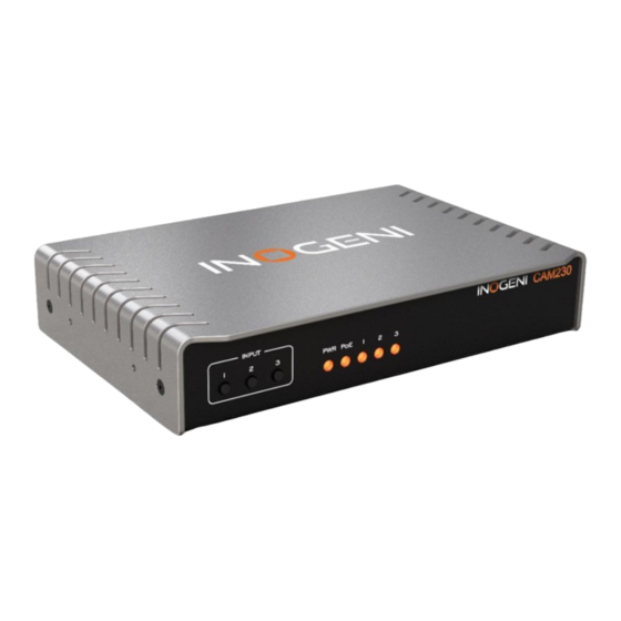
DEVICE INTERFACES Here are the devices interfaces. Figure 3: Front side connections Figure 4: Back side connections Input selection buttons Input status LEDs HDMI output USB2.0 camera output USB3.0 camera inputs HDMI camera input RS232 and remote interface LAN/PoE interface +12VDC power input... -
Page 6: Leds Behavior
LEDS BEHAVIOR Here are the LEDs behavior: Power input No power. SOLID Device is powered up. Not powered from PoE. SOLID Powered from PoE. Input led Input not detected and not selected. Input detected and not selected. HIGH Input selected. -
Page 7: Specifications
SPECIFICATIONS Here is the complete specification. Physical details 17.33 cm x 11.57 cm x 3.26 cm Dimensions (W x L x H) 6.82” x 4.55” x 1.28” 12V (100-240 VAC 50/60Hz to 12V/1.2A DC) – or – Power supply PoE source compliant with IEEE 802.3af (802.3at Type 1) Weight 600 g 1 x USB 2.0 Type-B to Type-A cable (3ft). - Page 8 Control Front buttons RS-232 Control options 100 Mbps half-duplex (autonegotiation not supported) IP interface Supports DHCP or static IP addressing Baud rate: 9600 Data bits: 8 RS232 interface Stop bits: 1 Parity: None Flow control: None Certifications The device does not decrypt BD/DVD movies, satellite/cable receivers or other HDCP compliant encrypted sources.
-
Page 9: Serial Communication Protocol
Pin 1: Receive Pin 2: GND Pin 3: Transmit Pin 4: 5V supply (for INOGENI Remote) There must be a space character between command and arguments. Typically, commands will return ACK in case of success and NACK in case of failure. -
Page 10: Inogeni Remote
1 => manual switching INOGENI REMOTE The INOGENI Remote needs to be connected to the terminal block port in order to operate. Apply wiring accordingly. This remote is sending serial commands to the device. Make sure to set the DIP SW6 below the device to ON in order to apply power to the remote before going further. -
Page 11: Lan Communication Protocol
You can access the device settings through its LAN interface. The LAN interface uses DHCP (default) and static IP addressing. You can obtain the IP from the Inogeni Control App or from the serial port IP command. Note that LAN is set to 100Mbps half-duplex. - Page 12 The STATUS page will give you information about the firmware installed. video and audio devices that you can monitor. Figure 5: Status preview...
- Page 13 The CONFIGURATION tab will allow you to : Set the HDMI resolution over HDMI Set the selected camera source Set the video input switching mode AUTO : Device will switch to newly detected video source MANUAL : Device will only switch when we get the control to do it. Set the audio input from USB sources or HDMI input.
- Page 14 The SYSTEM tab will allow you to : Change the current password for accessing device settings. Get/Set REST API access token needed using REST API interface. Change network settings of your device. Restore default settings and reboot the system. Update your system. Figure 7: System preview...
- Page 15 Click on the “Choose File” button and browse to the WIC file downloaded from our website. Click on “Update CAM230” button to proceed to the update. The operation can take up to 1 minute. The device will reboot and browser will be refreshed.
- Page 16 The DOCUMENTATION tab will allow you : Get to the latest user guide. Go to product webpage. Figure 8: Documentation preview The first time you access the webpage, your web browser is likely to complain that the connection is insecure. The reason for this is because we are using self-signed HTTPS certificate, because certificate providers will not provide certificates for address that are not globally accessible.
-
Page 17: Rest Api
REST API The response will usually be JSON formatted with a “message” field containing a JSON string explaining the cause of the error or “success” in case of success. Note that we are using self-signed certificates. You can enable a bearer authentication in the HTTP header (Authorization: Bearer <token>) through our configuration page to increase security on the API. - Page 18 GET/POST mode=<mode> "message": <String> https://<IP>/api/v1/setHdmi <mode> options: 0 => 1080P60 Set HDMI output mode 1 => 1080P50 2 => 720P60 3 => 720P50 4 => 4K24 5 => 4K25 6 => 4K30 GET/POST x-www-form-urlencoded input=<inputPort> "message": <String> https://<IP>/api/v1/ format=<formatIndex> setVideoFormat <inputPort>...
- Page 19 serialWrite Write serial data to RS232. Giving content to write in URL is not supported. GET/POST x-www-form-urlencoded mode=<static,dhcp> "message": <String> https://<IP>/api/v1/setNetwork If mode is static, must provide following args: ip=<ipv4 address> Configure network settings netmask=<ipv4 netmask> If mode is static, you can also specify a gateway: gateway=<ipv4 gateway>...
-
Page 20: Inogeni Control App
You can use our Control App to monitor firmware information and upgrade your unit. NOTE: You need to use the USB-B to USB-A cable provided with the box for the Control App to detect the unit. Figure 9: INOGENI Control App preview... -
Page 21: Mechanical Specifications
MECHANICAL SPECIFICATIONS You can find the mechanical specification here that lists the holes. All dimensions are in mm [in]. M2.5 screw holes for future brackets Figure 10: Top plate dimensions... -
Page 22: Dip Switches
4x M2.5 mounting holes Figure 11: Bottom plate dimensions and holes positions DIP SWITCHES Here you can find the behavior of the DIP switches located at the back of the unit. Switch Position Description For future use. For future use. For future use. -
Page 23: Troubleshooting Section
Unfortunately, this is the expected behavior since the PC is agnostic of the USB computer is not detecting the camera camera. However, the device supports all UVC controls (pan, tilt and zoom while the CAM230 is connected in controls) and can route them to the selected camera. line. -
Page 24: Support
© Copyright 2023 by INOGENI INC. All Rights Reserved. INOGENI name and logo are trademarks or registered trademark of INOGENI. Use of this product is subject to the terms and conditions of the license and limited warranty in effect at the time of purchase. Product specifications can change without notice.
Need help?
Do you have a question about the CAM230 and is the answer not in the manual?
Questions and answers