Table of Contents
Advertisement
Quick Links
Advertisement
Table of Contents

Related Manuals for inogeni TOGGLE


Summary of Contents for inogeni TOGGLE
- Page 1 INOGENI TOGGLE User guide Version 1.7 1/7/22...
-
Page 2: Table Of Contents
Block Diagram ................................2 Device interfaces ................................3 Leds behavior ................................4 Operating modes ................................4 Specifications ................................. 5 Serial communication protocol ............................6 GPIN Mode ..................................7 Important Notes about GPIN ............................. 7 Settings..................................8 INOGENI Control App ..............................9 Support..................................10... -
Page 3: Typical Application
TYPICAL APPLICATION Here is a typical connection diagram used for the TOGGLE device in a videoconferencing setup. BLOCK DIAGRAM Here is a simple block diagram of the TOGGLE unit. USB device1 USB device 2 USB 3.0/2.0 USB device 3 Control:... -
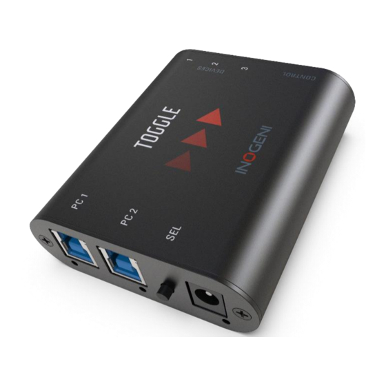
Page 4: Device Interfaces
DEVICE INTERFACES Here are the devices interfaces. RS232 and GPIN interfaces 3 x USB-A ports for devices PC #1 USB-B port PC #2 USB-B port Push-button +12V power input PC #1 led indicator PC #2 led indicator Power indicator... -
Page 5: Leds Behavior
The manual mode will enable you to force a specific PC selection. Push-button action and remote control are also supported. It is possible to turn OFF both PCs in manual mode. These modes can be set through our INOGENI Control App or through the RS232 interface. The mode will be saved onboard the device. -
Page 6: Specifications
You can monitor current consumption through RS232 and our Control App. Software Upgrade Field upgradable through our INOGENI Control App. Automatic, manual or remote control. Control Current configuration is saved onboard. Please use the Control App from INOGENI to identify the hardware revision of your product. -
Page 7: Serial Communication Protocol
SERIAL COMMUNICATION PROTOCOL Here is the complete list of commands provided through the serial connection. Pinout is indicated on the enclosure. Connect to controller TX pin Connect to controller GND pin Connect to controller RX pin Baud rate: 9600 // Data bits: 8 // Stop bits: 1 // Parity: None // Flow control: None Commands Arguments Return... -
Page 8: Gpin Mode
Get GPIN mode (pulse =’0’, level = ‘1’) GGMOD Get HUB power status. If report ‘0’, then the HUB had GHPW 1,2,3 turned OFF the specified USB port (overcurrent). SAVE Save settings. Set/clear events (prints). Set/clear manual mode.(auto=’0’, manual=’1’) Get manual mode status. Force factory default settings Reset MCU. -
Page 9: Settings
It is recommended to set the Toggle in manual mode with the UART command “sm” when using the GPIN (especially with level mode). If the Toggle is used in auto mode, any changes on the PCx side will affect the PC selected even if the GPIN level mode is used. -
Page 10: Inogeni Control App
INOGENI CONTROL APP You can use our Control App to monitor firmware information, upgrade and configure your unit. NOTE: You need to use the USB-B to USB-A cable provided with the box for the Control App to detect the unit. -
Page 11: Support
© Copyright 2022 by INOGENI INC. All Rights Reserved. INOGENI name and logo are trademarks or registered trademark of INOGENI. Use of this product is subject to the terms and conditions of the license and limited warranty in effect at the time of purchase. Product specifications can change without notice.
Need help?
Do you have a question about the TOGGLE and is the answer not in the manual?
Questions and answers