Table of Contents
Advertisement
Available languages
Available languages
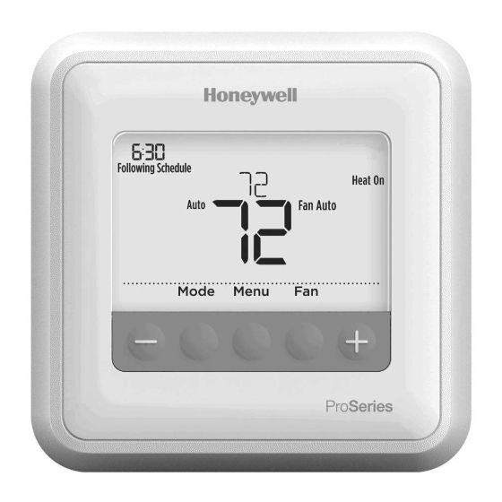
T4 Pro
Programmable Thermostat
Installation Instructions
Package Includes:
• T4 Pro Thermostat
• UWP™ Mounting System
• Honeywell Standard Installation
Adapter (J-box adapter)
• Honeywell Decorative Cover Plate –
Small; size 4-49/64 in x 4-49/64 in x
11/32 in (121 mm x 121 mm x 9 mm)
• Screws and anchors
• 2 AA Batteries
• Installation Instructions and User
Guide
Optional Cover Plate installation
NOTE: If Optional Cover Plate is not required,
see "UWP Mounting System installation" on
next page.
Use the Optional Cover Plate when:
• Mounting the thermostat to an electrical
junction box
• Or when you need to cover paint gap from
old thermostat.
1. Before starting, turn the power off at
the breaker box or switch. Separate the
Junction Box Adapter from the Cover
Plate. See Figure 1.
2. Mount the Junction Box Adapter to the
wall or an electrical box using any of the
eight screw holes. Insert and tighten
mounting screws supplied with Cover
Plate Kit. Do not overtighten. See Figure 2.
Make sure the Adapter Plate is level.
3. Attach the UWP by hanging it on the top
hook of the Junction Box Adapter and
then snapping the bottom of the UWP in
place. See Figure 3.
4. Snap the Cover Plate onto the Junction
Box Adapter. See Figure 4.
1
2
Use 2x
supplied
screws #6
5/8"
4
3
Advertisement
Table of Contents

Related Manuals for Honeywell Home TH4110U2005/U


Summary of Contents for Honeywell Home TH4110U2005/U
- Page 1 T4 Pro Programmable Thermostat Installation Instructions Package Includes: • T4 Pro Thermostat • UWP™ Mounting System • Honeywell Standard Installation Adapter (J-box adapter) • Honeywell Decorative Cover Plate – Small; size 4-49/64 in x 4-49/64 in x 11/32 in (121 mm x 121 mm x 9 mm) •...
-
Page 2: Power Options
UWP Mounting System installation 1. Before starting, turn the power off at the breaker box or switch. Open package to find the UWP. See Figure 5. 2. Position the UWP on wall. Level and mark hole positions. See Figure 6. Drill holes at marked positions, and then lightly tap supplied wall anchors into the wall using a hammer. - Page 3 Setting Slider Tabs (built-in jumper) Set R Slider Tab. UWP Mounting System • Use built-in jumper (R Slider Tab) to differentiate between one or two transformer systems. • If there is only one R wire, and it is connected to the R, Rc, or RH terminal, set the slider to the up position (1 wire).
- Page 4 Wiring conventional systems: forced air and hydronics 1H/1C System (1 transformer) 1H/1C System (2 transformers) Power [1] Power (heating transformer) [1] [R+Rc joined by Slider Tab] [2] Power (cooling transformer) [1] Compressor contactor Compressor contactor 24VAC common [3] 24VAC common [3, 4] Heat relay Heat relay Fan relay...
-
Page 5: Thermostat Mounting
Thermostat mounting 1. Push excess wire back into the wall opening. 2. Close the UWP door. It should remain closed without bulging. 3. Align the UWP with the thermostat, and push gently until the thermostat snaps in place. 4. Turn the power on at the breaker box or switch. - Page 6 Installer setup (ISU) 1 Press and hold CENTER and buttons for approximately 3 seconds to enter advanced menu. 2 Press Select to enter ISU. 3 Press Select to cycle through menu setup options. 4 Press to change values or select from available options.
- Page 7 Advanced setup options (ISU) (continued) # ISU ISU Name ISU Options (factory default in bold) Heating Equipment Type Conventional Forced Air Heat: 1 = Standard Efficiency Gas Forced Air 2 = High Efficiency Gas Forced Air 3 = Oil Forced Air 4 = Electric Forced Air 5 = Hot Water Fan Coil Heat Pump:...
- Page 8 Advanced setup options (ISU) (continued) # ISU ISU Name ISU Options (factory default in bold) 0 = Off Upstage Timer for Backup 5 = 90 minutes Heat (TH4210U only) 1 = 30 minutes 6 = 2 hours 2 = 45 minutes 7 = 3 hours 3 = 60 minutes 8 = 4 hours...
- Page 9 Advanced setup options (ISU) (continued) # ISU ISU Name ISU Options (factory default in bold) Number of Air Filters 0 - 2 Note: This ISU refers to the number of air filters in the system. 0 = Off Air Filter 1 Replacement 10 = 45 Calendar Days Reminder 1 = 10 Run Time Days...
-
Page 10: System Test
Installer system test To perform a System Test: 1 Press and hold CENTER and buttons for approximately 3 seconds to enter advanced menu. 2 Use to go to TEST. Press Select to enter System Test. 3 Use to change between Heat, Cool, Fan, Em. -
Page 11: Specifications
Specifications Temperature Ranges Heat: 40 °F to 90 °F (4.5 °C to 32.0 °C) Cool: 50 °F to 99 °F (10.0 °C to 37.0 °C) Operating Ambient Temperature 37 °F to 102 °F (2.8 °C to 38.9 °C) Shipping Temperature -20 °F to 120 °F (-28.9 °C to 48.9 °C) Operating Relative Humidity 5% to 90% (non-condensing) -
Page 12: Customer Assistance
CAUTION: ELECTRICAL HAZARD Can cause electrical shock or equipment damage. Disconnect power before beginning installation. CAUTION: EQUIPMENT DAMAGE HAZARD Compressor protection is bypassed during testing. To prevent equipment damage, avoid cycling the compressor quickly. CAUTION: MERCURY NOTICE If this product is replacing a control that contains mercury in a sealed tube, do not place the old control in the trash. -
Page 13: Notice D'installation
T4 Pro Thermostat programmable Notice d’installation La boîte comprend : • Thermostat T4 Pro • Système de montage UWP • Adaptateur d’installation standard Honeywell (adaptateur boîtier de raccordement) • Plaque de couvercle décorative Honeywell – Petite; dimension 4-49/64 in x 4-49/64 in x 11/32 in (121 mm x 121 mm x 9 mm). -
Page 14: Options D'alimentation
Installation du système de montage UWP 1. Avant le démarrage, éteindre l’alimentation au niveau du disjoncteur du circuit ou de l’interrupteur. Ouvrir l’emballage du UWP. Voir la Figure 5. 2. Placer le UWP sur le mur. Le mettre à niveau et marquer les positions des trous. - Page 15 Réglages des curseurs (cavalier intégré) Régler le curseur R. Système de montage UWP • Utiliser le commutateur de liaison intégré (curseur R) pour différencier entre un l’autre système de transformateur. • S’il n’y a qu’un seul fil R et s’il est connecté à...
- Page 16 Câblage des systèmes conventionnels : air forcé et hydronique Système à 1 étage de chauffage/1 étage de Système à 1 étage de chauffage/1 étage de refroidissement (1 transformateur) refroidissement (2 transformateurs) Alimentation [1] Alimentation (transformateur de chauffage) [1] [R+Rc liés par le curseur] [2] Alimentation (transformateur de refroidissement) [1] Contacteur du compresseur...
- Page 17 Montage du thermostat 1. Repousser le fil en excès dans l’ouverture du mur. 2. Fermer le couvercle du UWP. Elle doit rester fermée sans renflement. 3. Aligner l’UWP sur le thermostat, et appuyer doucement jusqu’à ce que le thermostat s’enclenche en place. 4.
- Page 18 Configuration de l’installateur (ISU) 1 Appuyer sur CENTER (Centre) et sur les boutons pendant 3 secondes environ pour accéder au menu des réglages avancés. 2 Appuyer sur Select (Sélectionner) pour accéder à ISU (Configuration de l’installateur). 3 Appuyer sur Select (Sélectionner) pour faire défiler les options de configuration du menu.
- Page 19 Options de configuration avancées (ISU) (suite) N° ISU Nom ISU Options ISU (réglage d’usine en gras) Chauffage à air pulsé conventionnel : 1 = Air pulsé à gaz efficacité standard 2 = Air pulsé à gaz haute efficacité 3 = Air pulsé au mazout 4 = Air pulsé...
- Page 20 Options de configuration avancées (ISU) (suite) N° ISU Nom ISU Options ISU (réglage d’usine en gras) 1 - 6 Remarque : Cette configuration installateur (ISU) ne s’affiche que lorsque la phase de refroidissement ou la phase du compresseur est réglée à la phase 1.
- Page 21 Options de configuration avancées (ISU) (suite) N° ISU Nom ISU Options ISU (réglage d’usine en gras) 0 = Aucun 1 = Partiel 2 = Total Remarque Déverrouillé : l’utilisateur a accès à tous les paramètres du thermostat. Verrouillage partiel : l’utilisateur ne peut modifier que les paramètres de Verrouillage du clavier température.
- Page 22 Test du système de l’installateur Pour réaliser un test du système : 1 Appuyer sur CENTER (Centre) et sur les boutons pendant 3 secondes environ pour accéder au menu des réglages avancés. 2 Utiliser pour passer à TEST. Appuyer sur Select (Sélectionner) pour accéder au test du système.
-
Page 23: Caractéristiques Techniques
Caractéristiques techniques Plages de température Chauffage : 40 °F à 90 °F (4,5 °C à 32,0 °C) Refroidissement : 50 °F à 99 °F (10,0 °C à 37,0 °C) Température de service 37 °F à 102 °F (2,8 °C à 38,9 °C) Température d’expédition -20 °F à... -
Page 24: Service À La Clientèle
MISE EN GARDE: RISQUE DE CHOC ÉLECTRIQUE Peut provoquer des chocs électriques ou endommager le matériel. Couper l’alimentation électrique avant d’effectuer le raccordement. MISE EN GARDE: RISQUE DE DOMMAGES DE L’ÉQUIPEMENT La protection du compresseur est annulée durant le test. Pour éviter d’endommager l’équipement, éviter d’actionner le compresseur trop rapidement. -
Page 25: Instrucciones Para La Instalación
T4 Pro Termostato programable Instrucciones para la instalación El paquete incluye: • Termostato T4 Pro ™ • Sistema de montaje UWP • Adaptador de instalación estándar de Honeywell (adaptador para cajetín de empalmes) • Placa de cubierta decorativa Honeywell – pequeña;... - Page 26 Instalación del sistema de montaje con UWP 1. Antes de comenzar, desconecte el suministro de electricidad en la caja de interruptores de circuito o el interruptor. Abra el paquete para encontrar la UWP. Consulte la Figura 1. 2. Coloque la UWP en la pared. Nivele y marque la posición de los tornillos.
- Page 27 Configuración de las lengüetas de los controles deslizantes (puente incorporado) Configure la lengüeta del control Sistema de montaje con UWP deslizante R. • Utilice el puente integrado (lengüeta deslizante R) para diferenciar entre uno o dos sistemas de transformadores. • Si hay solo un cable R y está conectado al terminal R, Rc o RH, coloque el control deslizante en la posición superior (1 cable).
- Page 28 Cableado de sistemas convencionales: aire forzado e hidrónico Sistema de 1 etapa de calefacción/1 etapa de Sistema de 1 etapa de calefacción/1 etapa de refrigeración (1 transformador) refrigeración (2 transformadores) Alimentación (transformador de Alimentación [1] calefacción) [1] [R+Rc unidos por la lengüeta del Alimentación (transformador de control deslizante] [2] refrigeración) [1]...
-
Page 29: Montaje Del Termostato
Montaje del termostato 1. Introduzca el excedente de cable en la abertura de la pared. 2. Cierre la tapa de la placa de la UWP. Debe permanecer cerrada sin quedar protuberante. 3. Alinee la UWP con el termostato y presione suavemente hasta que el termostato calce en su lugar. - Page 30 Configuración por el instalador (ISU) 1 Presione y sostenga CENTER (centro) y los botones durante aproximadamente 3 segundos para ingresar al menú avanzado. 2 Presione Select (seleccionar) para ingresar al ISU. 3 Presione Select (seleccionar) para avanzar a través de las opciones del menú de configuración. 4 Presione para cambiar los valores o seleccionar las opciones disponibles.
- Page 31 Opciones avanzadas de configuración (ISU) (continuado) N.º del ISU Nombre del ISU Opciones del ISU (las configuraciones predeterminadas de fábrica están en negrita) Calefacción de aire forzado convencional: 1 = Aire forzado por gas de eficiencia estándar 2 = Aire forzado por gas de alta eficiencia 3 = Aire forzado por aceite 4 = Aire forzado por electricidad 5 = Serpentín del ventilador agua caliente...
- Page 32 Opciones avanzadas de configuración (ISU) (continuado) N.º del ISU Nombre del ISU Opciones del ISU (las configuraciones predeterminadas de fábrica están en negrita) 1 - 6 Nota: este ISU solo se muestra si se configuró la fase de compresión o de refrigeración como 1 fase.
- Page 33 Opciones avanzadas de configuración (ISU) (continuado) N.º del ISU Nombre del ISU Opciones del ISU (las configuraciones predeterminadas de fábrica están en negrita) 0 = Ninguno 1 = Parcial 2 = Lleno Nota: Desbloqueado: el usuario tiene acceso a todas las configuraciones del termostato.
- Page 34 Prueba del sistema por parte del instalador Para realizar una prueba del sistema: 1 Presione y sostenga CENTER (centro) y los botones durante aproximadamente 3 segundos para ingresar al menú avanzado. para ir a TEST (prueba). Presione Select 2 Use (seleccionar) para iniciar la prueba del sistema.
-
Page 35: Especificaciones
Especificaciones Rangos de temperatura Calefacción: de 40 °F a 90 °F (4.5 °C a 32.0 °C) refrigeración : de 50 °F a 99 °F (10.0 °C a 37.0 °C) Temperatura ambiente de funcionamiento de 37 °F a 102 °F (de 2.8 °C a 38.9 °C) Temperatura de envío de -20 °F a 120 °F (de -28.9 °C a 48.9 °C) Humedad relativa de funcionamiento... -
Page 36: Asistencia Al Cliente
PRECAUCIÓN: PELIGRO DE ELECTROCUCIÓN Puede causar descargas eléctricas o daños al equipo. Desconecte el suministro eléctrico antes de comenzar la instalación. PRECAUCIÓN: RIESGOS DE DAÑOS AL EQUIPO Se evita la protección del compresor durante la prueba. Para prevenir daños al equipo, evite encender y apagar rápidamente el compresor. PRECAUCIÓN: AVISO SOBRE EL MERCURIO Si este producto está...
Need help?
Do you have a question about the TH4110U2005/U and is the answer not in the manual?
Questions and answers
Having hit a wrong combination the thermostat is stuck between a random number 0-9 and a locked screen. Reset doesn’t seem to work. How do I start the thermostat menu again?
To reset the Honeywell Home TH4110U2005/U thermostat, follow these steps:
1. Press and hold the two designated buttons to access the advanced setup options (ISU).
2. Navigate using the right arrow until you see "Restore Default."
3. Select "Restore Default" to factory reset the thermostat.
4. Alternatively, if you only want to reset the schedule, select "Restore Schedule."
5. After completing the reset, press the Home button to return to the main screen.
This will restore the thermostat to its default settings and allow access to the menu again.
This answer is automatically generated
What does the ISU 225 stand for