Moto XFB Owner's Manual
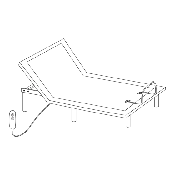
Low-profile bed
Hide thumbs
Also See for XFB:
- Owner's manual (14 pages) ,
- Owner's manual (11 pages) ,
- Owner's manual (11 pages)
Advertisement
Quick Links
Advertisement

Related Manuals for Moto XFB


Summary of Contents for Moto XFB
- Page 1 OWNER’S MANUAL XFB/XSF/SFL Low-Prof ile Bed LPB2NM Rev 6.0 08/2023...
- Page 2 Setup the power foundation without the bed frame. Take out all the accessories from the packaging and put them aside. All electronics and components that need to be installed are located in boxes Open the box lid. under the foundation or attached to the frame. Before discarding the packing materials, ensure that all the parts are accounted for.
- Page 3 WARNING! FAILURE TO FOLLOW THIS STEP WILL RESULT IN DAMAGE TO YOUR POWER FOUNDATION. PLEASE MAKE SURE YOU FOLLOW THE INSTRUCTIONS CAREFULLY BEFORE UNFOLDING YOUR POWER FOUNDATION. Remove the red plastic Turn the locking pin 90° in Remove the folding locking safety clip.
- Page 4 Connect the hand control and secure it with the connector lock. Uncoil the AC power cord, connect the DC power cord to the power supply and then connect the power supply to the AC A R D power source. D B O H E A Power Supply DC Power Cord...
- Page 5 Setup the power foundation with the bed frame and slat base. *NOTE: Optional parts are required. Take the bed out of the box, put it on the slat base, Connect the hand control and secure it with the connector lock. do not install any legs.
- Page 6 Turn over the bed. Install the middle stabilizer bracket as shown. (*Optional parts are required to perform this setup. ) Metal Frame Of The Bed A R D D B O Screws H E A ST4.2×16 Slat Base WARNING! FAILURE TO FOLLOW THIS STEP WILL RESULT IN DAMAGE TO YOUR POWER FOUNDATION. PLEASE MAKE SURE YOU FOLLOW THE INSTRUCTIONS CAREFULLY BEFORE UNFOLDING YOUR POWER FOUNDATION.
- Page 7 Make the bed completely flat with a flipping motion. Install the mattress retainer bar one side after another. A R D A R D D B O D B O H E A H E A Connect the power supply to the AC power source. AC Power Source A R D D B O...
- Page 8 Lift the head of the bed by hand control. Install the two stabilizer brackets as shown. (*Optional parts are required to perform this setup. ) O A R M8*16 Bolts H E A Washers Screws ST4.2×16 DONE! Hand Control Instructions ADJUST Lifts Head This button lifts the head section of the foundation.
- Page 9 Parts List Headboard Bracket Installation Guide (Optional) Headboard brackets are optional and not included. A 1/2” (13 mm) socket and 1/2” (13 mm) wrench are required to complete the installation. (2) T-Brackets (8) M8*16 (4) Nuts (4) Washers (2) Headboard Brackets INCLUDED WITH POWER FOUNDATION Hand Control AC Power Cord...
- Page 10 Spacing Connector for TXL/T/CKS (Optional) Product Serial Number (Figure B) Install two spacing connectors to ensure the gap between the two Each power foundation has its unique serial number. The serial adjustable bases is consistent. number can be found on the metal (2) SPACING CONNECTOR (TXL/T/CKS ONLY) frame near the legs at the foot area.
Need help?
Do you have a question about the XFB and is the answer not in the manual?
Questions and answers