GIGABYTE Z590 AORUS XTREME WATERFORCE - Motherboard Manual
- User manual (108 pages) ,
- Manual (10 pages) ,
- User manual (52 pages)
Advertisement
- 1 Identifying Your Motherboard Revision
- 2 Box Contents
- 3 Optional Items
- 4 Z590 AORUS XTREME WB (Z590 AORUS XTREME WATERFORCE) Motherboard Layout
- 5 Z590 AORUS XTREME WB (Z590 AORUS XTREME WATERFORCE) Motherboard Block Diagram
-
6
Hardware Installation
- 6.1 Installation Precautions
- 6.2 Product Specifications
- 6.3 Installing the CPU and CPU Cooler
- 6.4 Installing the Memory
- 6.5 Installing an Expansion Card
- 6.6 Setting up an AMD CrossFire Configuration
- 6.7 Back Panel Connectors
- 6.8 Onboard Buttons and Switches
-
6.9
Internal Connectors
- 6.9.1 ATX_12V_2X4_1/ATX_12V_2X4_2/ATX (2x4 12V Power Connectors and 2x12 Main Power Connector)
- 6.9.2 CPU_FAN/SYS_FAN1/2/3/4/7/8 (Fan Headers)
- 6.9.3 SYS_FAN5_PUMP/SYS_FAN6_PUMP (System Fan/Water Cooling Pump Headers)
- 6.9.4 CPU_OPT (Water Cooling CPU Fan Header)
- 6.9.5 LED_CPU (Water Cooling Kit CPU LED Header)
- 6.9.6 LED_PCH (Water Cooling Kit Chipset LED Header)
- 6.9.7 NOISE_SENSOR (Noise Detection Header)
- 6.9.8 EC_TEMP1/EC_TEMP2 (Temperature Sensor Headers)
- 6.9.9 LED_C1/LED_C2 (Integrated Extension Cable Headers for Addressable and RGB LED Strips)
- 6.9.10 BAT (Battery)
- 6.9.11 SATA3 0/1/2/3/4/5 (SATA 6Gb/s Connectors)
- 6.9.12 M2A_SB/M2P_CPU (Note)/M2M_SB (M.2 Socket 3 Connectors)
- 6.9.13 F_PANEL (Front Panel Header)
- 6.9.14 F_AUDIO (Front Panel Audio Header)
- 6.9.15 F_U320G (USB Type-C Header with USB 3.2 Gen 2x2 Support)
- 6.9.16 F_U32 (USB 3.2 Gen 1 Header)
- 6.9.17 F_USB1 (USB 2.0/1.1 Header)
- 7 BIOS Setup
- 8 Configuring a RAID Set
- 9 Drivers Installation
- 10 Unique Features
- 11 Configuring Audio Input and Output
- 12 Troubleshooting
- 13 Debug LED Codes
- 14 Contact Us
- 15 Documents / Resources
Identifying Your Motherboard Revision
The revision number on your motherboard looks like this: "REV: X.X." For example, "REV: 1.0" means the revision of the motherboard is 1.0. Check your motherboard revision before updating motherboard BIOS, drivers, or when looking for technical information.
Example:

Box Contents
- Z590 AORUS XTREME WB (Z590 AORUS XTREME WATERFORCE) motherboard
- One water cooling kit
- One AORUS USB flash drive with drivers
- User's Manual
- Quick Installation Guide
- Six SATA cables
- Two antennas
- Two integrated extension cables for addressable and RGB LED strips
- One AORUS RGB Fan Commander
- One front panel extension cable
- One front USB header extension cable
- One ESSential USB DAC
- One noise detection cable
- Two thermistor cables
- One G Connector
- Two Velcro Cable Ties
- M.2 screws
- One AORUS Gen4 AIC Adaptor (GC-2XM2G4)
The box contents above are for reference only and the actual items shall depend on the product package you obtain. The box contents are subject to change without notice.
Optional Items
- 2-port USB 2.0 bracket (Part No. 12CR1-1UB030-6*R)
- eSATA bracket (Part No. 12CF1-3SATPW-4*R)
- 3.5" Front Panel with 2 USB 3.2 Gen 1 ports (Part No. 12CR1-FPX582-2*R)
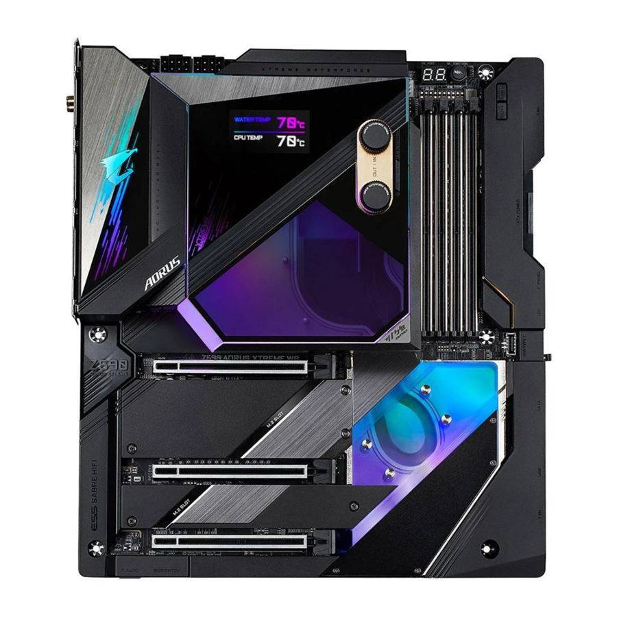
Z590 AORUS XTREME WB (Z590 AORUS XTREME WATERFORCE) Motherboard Layout

(Note) For debug code information, please refer to Debug LED Codes.
Z590 AORUS XTREME WB (Z590 AORUS XTREME WATERFORCE) Motherboard Block Diagram

(Note) Actual support may vary by CPU.
Hardware Installation
Installation Precautions
The motherboard contains numerous delicate electronic circuits and components which can become damaged as a result of electrostatic discharge (ESD). Prior to installation, carefully read the user's manual and follow these procedures:
- Prior to installation, make sure the chassis is suitable for the motherboard.
- Prior to installation, do not remove or break motherboard S/N (Serial Number) sticker or warranty sticker provided by your dealer. These stickers are required for warranty validation.
- Always remove the AC power by unplugging the power cord from the power outlet before installing or removing the motherboard or other hardware components.
- When connecting hardware components to the internal connectors on the motherboard, make sure they are connected tightly and securely.
- When handling the motherboard, avoid touching any metal leads or connectors.
- It is best to wear an electrostatic discharge (ESD) wrist strap when handling electronic components such as a motherboard, CPU or memory. If you do not have an ESD wrist strap, keep your hands dry and first touch a metal object to eliminate static electricity.
- Prior to installing the motherboard, please have it on top of an antistatic pad or within an electrostatic shielding container.
- Before connecting or unplugging the power supply cable from the motherboard, make sure the power supply has been turned off.
- Before turning on the power, make sure the power supply voltage has been set according to the local voltage standard.
- Before using the product, please verify that all cables and power connectors of your hardware components are connected.
- To prevent damage to the motherboard, do not allow screws to come in contact with the motherboard circuit or its components.
- Make sure there are no leftover screws or metal components placed on the motherboard or within the computer casing.
- Do not place the computer system on an uneven surface.
- Do not place the computer system in a high-temperature or wet environment.
- Turning on the computer power during the installation process can lead to damage to system components as well as physical harm to the user.
- If you are uncertain about any installation steps or have a problem related to the use of the product, please consult a certified computer technician.
- If you use an adapter, extension power cable, or power strip, ensure to consult with its installation and/or grounding instructions.
Product Specifications


(Note) Supported by 11th Generation processors only.
* GIGABYTE reserves the right to make any changes to the product specifications and product-related information without prior notice.

Please visit GIGABYTE's website for support lists of CPU, memory modules, SSDs, and M.2 devices.

Please visit the Support\Utility List page on GIGABYTE's website to download the latest version of apps.
Installing the CPU and CPU Cooler
 Read the following guidelines before you begin to install the CPU:
- Make sure that the motherboard supports the CPU.
(Go to GIGABYTE's website for the latest CPU support list.) - Always turn off the computer and unplug the power cord from the power outlet before installing the CPU to prevent hardware damage.
- Locate the pin one of the CPU. The CPU cannot be inserted if oriented incorrectly. (Or you may locate the notches on both sides of the CPU and alignment keys on the CPU socket.)
- Apply an even and thin layer of thermal grease on the surface of the CPU.
- Do not turn on the computer if the CPU cooler is not installed, otherwise overheating and damage of the CPU may occur.
- Set the CPU host frequency in accordance with the CPU specifications. It is not recommended that the system bus frequency be set beyond hardware specifications since it does not meet the standard requirements for the peripherals. If you wish to set the frequency beyond the standard specifications, please do so according to your hardware specifications including the CPU, graphics card, memory, hard drive, etc.
Installing the CPU
- Locate the alignment keys on the motherboard CPU socket and the notches on the CPU.

![]()
Please visit GIGABYTE's website for details on hardware installation. - Follow the steps below to correctly install the CPU into the motherboard CPU socket.
![warning]()
- Before installing the CPU, make sure to turn off the computer and unplug the power cord from the power outlet to prevent damage to the CPU.
- To protect the socket contacts, do not remove the protective plastic cover unless the CPU is inserted into the CPU socket. Save the cover properly and replace it if the CPU is removed.
Step 1:
Gently press the CPU socket lever handle down and away from the socket with your finger. Then completely lift the CPU socket lever and the metal load plate/plastic cover will be lifted as well.

Step 2:
Hold the CPU with your thumb and index fingers. Align the CPU pin one marking (triangle) with the pin one corner of the CPU socket (or you may align the CPU notches with the socket alignment keys) and gently insert the CPU into position.
![]()
Step 3:
Once the CPU is properly inserted, carefully replace the load plate. When replacing the load plate, make sure the front end of the load plate is under the shoulder screw. Then press the CPU socket lever. The protective plastic cover may pop off from the load plate during the process of engaging the lever. Remove the cover. (Save the cover properly and always replace it when the CPU is not installed.)
![]()
Step 4:
Finally, secure the lever under its retention tab to complete the installation of the CPU.
![]()
NOTE:
Hold the CPU socket lever by the handle, not the lever base portion.
![]()


Installing the Water Cooling Kit

- Before installing the water cooling kit, ensure the motherboard can boot normally.
- If you want to install an M.2 SSD, you have to install the M.2 SSD first before installing the water cooling kit.
- The water cooling kit provides a G1/4" inlet and a G1/4" outlet. Please choose the barbs (not included) that suit your requirements.
- Depending on your hardware requirements, apply appropriate amount of the provided thermal paste on the water cooling kit.
- After the water cooling kit is placed on the motherboard, press the OC Ignition button first and then press the power button to check whether the cooling fluid can be injected properly. Then complete the injection. Unplug the power supply and tighten the screws included in the water cooling kit. The type and number of the included screws are as below. Make sure you use the right screws before the installation:
Screw M2*6 M3*10.8 M3*6.5 (with washer) Reference Torque 2.0~2.5 (kgf-cm) 3.5~4.0 (kgf-cm) 3.5~4.0 (kgf-cm) Number 2 4 7
Refer to the pictures below to install the water cooling kit on the motherboard.
Step 1:
Carefully take the water cooling kit out of its package and remove the protective plastic films from the CPU area and thermal pads.

Step 2:
Before the installation, remove the side cover from the water cooling kit and save it properly. Align the water cooling kit with the motherboard in the direction as indicated below, connect the LED cable from the water cooling kit to the LED_PCH header. Then place the water cooling kit vertically on the motherboard. Tighten the two screws (M2*6) to secure the water cooling kit to the M.2 standoffs as indicated.

Step 3:
Carefully flip the motherboard over, fasten the CPU backplate using the four screws (M3*10.8) in a diagonal sequence.

Step 4:
Tighten the three screws (M3*6.5) with washers to the mounting holes in the CPU area (refer to the bottom left picture). Then tighten the four screws (M3*6.5) with washers to the mounting holes in the Chipset area in a diagonal sequence (refer to the bottom right picture). Make sure the water cooling kit is securely attached.

Step 5:
After installing the water cooling kit, connect the Type-C® cable on the side of the water cooling kit to the LED_CPU header on the motherboard and then replace the side cover. After completing the steps above, connect your water cooling components.

Installing the Memory
Read the following guidelines before you begin to install the memory:
- Make sure that the motherboard supports the memory. It is recommended that memory of the same capacity, brand, speed, and chips be used.
(Go to GIGABYTE's website for the latest supported memory speeds and memory modules.) - Always turn off the computer and unplug the power cord from the power outlet before installing the memory to prevent hardware damage.
- Memory modules have a foolproof design. A memory module can be installed in only one direction. If you are unable to insert the memory, switch the direction.
Dual Channel Memory Configuration
This motherboard provides four memory sockets and supports Dual Channel Technology. After the memory is installed, the BIOS will automatically detect the specifications and capacity of the memory. Enabling Dual Channel memory mode will double the original memory bandwidth.
The four memory sockets are divided into two channels and each channel has two memory sockets as following:
- Channel A: DDR4_A1, DDR4_A2
- Channel B: DDR4_B1, DDR4_B2

Due to CPU limitations, read the following guidelines before installing the memory in Dual Channel mode.
- Dual Channel mode cannot be enabled if only one memory module is installed.
- When enabling Dual Channel mode with two or four memory modules, it is recommended that memory of the same capacity, brand, speed, and chips be used.
Installing a Memory
Before installing a memory module, make sure to turn off the computer and unplug the power cord from the power outlet to prevent damage to the memory module. DDR4 and DDR3 DIMMs are not compatible to each other or DDR2 DIMMs. Be sure to install DDR4 DIMMs on this motherboard.

A DDR4 memory module has a notch, so it can only fit in one direction. Follow the steps below to correctly install your memory modules in the memory sockets.
Step 1:
Note the orientation of the memory module. Spread the retaining clip at the right end of the memory socket. Place the memory module on the socket. As indicated in the picture on the left, place your fingers on the top edge of the memory, push down on the memory and insert it vertically into the memory socket.

Step 2:
The clip at the right end of the socket will snap into place when the memory module is securely inserted.

Installing an Expansion Card
Read the following guidelines before you begin to install an expansion card:
- Make sure the motherboard supports the expansion card. Carefully read the manual that came with your expansion card.
- Always turn off the computer and unplug the power cord from the power outlet before installing an expansion card to prevent hardware damage.

Follow the steps below to correctly install your expansion card in the expansion slot.
- Locate an expansion slot that supports your card. Remove the metal slot cover from the chassis back panel.
- Align the card with the slot, and press down on the card until it is fully seated in the slot.
- Make sure the metal contacts on the card are completely inserted into the slot.
- Secure the card's metal bracket to the chassis back panel with a screw.
- After installing all expansion cards, replace the chassis cover(s).
- Turn on your computer. If necessary, go to BIOS Setup to make any required BIOS changes for your expansion card(s).
- Install the driver provided with the expansion card in your operating system.
Example: Installing and Removing a PCI Express Graphics Card:
- Installing a Graphics Card:
Gently push down on the top edge of the card until it is fully inserted into the PCI Express slot. Make sure the card is securely seated in the slot and does not rock.

- Removing the Card:
Gently push back on the lever on the slot and then lift the card straight out from the slot.
![]()


Setting up an AMD CrossFire™ Configuration
System Requirements
- Windows 10 64-bit operating system
- A CrossFire-supported motherboard with two PCI Express x16 slots and correct driver
- CrossFire-ready graphics cards of identical brand and chip and correct driver
- CrossFire(Note) bridge connectors
- A power supply with sufficient power is recommended (Refer to the manual of your graphics cards for the power requirement)
Connecting the Graphics Cards
Step 1:
Observe the steps in "Installing an Expansion Card" and install the graphics cards on the PCIEX16 and PCIEX8 slots.
Step 2:
Insert the CrossFire(Note) bridge connectors in the CrossFire gold edge connectors on top of the cards.
Step 3:
Plug the display cable into the graphics card on the PCIEX16 slot.
Configuring the Graphics Card Driver
To Enable CrossFire Function
After installing the graphics card driver in the operating system, go to the AMD RADEON SETTINGS screen. Browse to Gaming\Global Settings and ensure AMD CrossFire is set to On.

(Note) The bridge connector(s) may be needed or not depending on your graphics cards.
Procedure and driver screen for enabling CrossFire technology may differ by graphics cards and driver version. Refer to the manual that came with your graphics cards for more information about enabling CrossFire technology.
Back Panel Connectors

- Q-Flash Plus Button (Note)
This button allows you to update the BIOS when the power connector is connected but the system is not powered on. - Clear CMOS Button
Use this button to clear the CMOS values (e.g. BIOS configuration) and reset the CMOS values to factory defaults when needed.
![warning]()
- Always turn off your computer and unplug the power cord from the power outlet before using the clear CMOS button.
- Do not use the clear CMOS button when the system is on, or the system may shutdown and data loss or damage may occur.
- After system restart, go to BIOS Setup to load factory defaults (select Load Optimized Defaults) or manually configure the BIOS settings (refer to Chapter "BIOS Setup," for BIOS configurations).
- SMA Antenna Connectors (2T2R)
Use this connector to connect an antenna.
![]() Tighten the antennas to the antenna connectors and then aim the antennas correctly for better signal reception.
Tighten the antennas to the antenna connectors and then aim the antennas correctly for better signal reception. - RJ-45 LAN Port (LAN2)
The Gigabit Ethernet LAN port provides Internet connection at up to 2.5 Gbps data rate. The following describes the states of the LAN port LEDs.
")
- USB 3.2 Gen 2 Type-A Port (Red)
The USB 3.2 Gen 2 port supports the USB 3.2 Gen 2 specification and is compatible to the USB 3.2 Gen 1 and USB 2.0 specification. Use this port for USB devices. - Thunderbolt™ 4 Connector (USB Type-C® Port)
The connector supports standard DisplayPort and Thunderbolt™ video outputs. You can connect a standard DisplayPort/Thunderbolt™ monitor to this connector with an adapter. The Thunderbolt™ connector can daisy chain up to five Thunderbolt™ devices. Because of the limited I/O resources of the PC architecture, the number of Thunderbolt™ devices that can be used is dependent on the number of the PCI Express devices being installed. You can adjust the Thunderbolt™ settings under Settings\Thunderbolt Configuration in BIOS Setup. The maximum supported resolution is 5120 x 2880@60 Hz with 24 bpp via single display output, but the actual resolutions supported are dependent on the monitor being used. Also, the connector is reversible and supports the USB 3.2 Gen 2 specification and is compatible to the USB 3.2 Gen 1 and USB 2.0 specification. You can use this port for USB devices, too. - RJ-45 LAN Port (LAN1)
The Gigabit Ethernet LAN port provides Internet connection at up to 10 Gbps data rate. The following describes the states of the LAN port LEDs.
")
- USB 3.2 Gen 2 Type-A Port (Red) (Q-Flash Plus Port)
The USB 3.2 Gen 2 port supports the USB 3.2 Gen 2 specification and is compatible to the USB 3.2 Gen 1 and USB 2.0 specification. Use this port for USB devices. Before using Q-Flash Plus (Note), make sure to insert the USB flash drive into this port first. - HDMI Port
![]()
The HDMI port supports HDCP 2.3 and Dolby TrueHD and DTS HD Master Audio formats. It also supports up to 192KHz/16bit 7.1-channel LPCM audio output. You can use this port to connect your HDMI-supported monitor. The maximum supported resolution is 4096x2160@30 Hz, but the actual resolutions supported are dependent on the monitor being used.
![]() After installing the HDMI device, make sure to set the default sound playback device to HDMI. (The item name may differ depending on your operating system.)
After installing the HDMI device, make sure to set the default sound playback device to HDMI. (The item name may differ depending on your operating system.) - Center/Subwoofer Speaker Out
Use this audio jack to connect center/subwoofer speakers. - Rear Speaker Out
Use this audio jack to connect rear speakers. - Optical S/PDIF Out Connector
This connector provides digital audio out to an external audio system that supports digital optical audio. Before using this feature, ensure that your audio system provides an optical digital audio in connector. - Line In/Side Speaker Out
The line in jack. Use this audio jack for line in devices such as an optical drive, walkman, etc. - Line Out/Front Speaker Out
The line out jack. - Mic In
The Mic in jack.
Audio Jack Configurations:

![]() If you want to install a Side Speaker, you need to retask the Line in jack to be Side Speaker out through the audio driver.
If you want to install a Side Speaker, you need to retask the Line in jack to be Side Speaker out through the audio driver.
![warning]()
- When removing the cable connected to a back panel connector, first remove the cable from your device and then remove it from the motherboard.
- When removing the cable, pull it straight out from the connector. Do not rock it side to side to prevent an electrical short inside the cable connector.
")
")


(Note) To enable Q-Flash Plus function, refer to Chapter "Unique Features," for more information.
Onboard Buttons and Switches
BIOS Switches
The BIOS switch (BIOS_SW) allows users to easily select a different BIOS for boot up or overclocking, helping to reduce BIOS failure during overclocking. The SB switch allows enabling or disabling of the Dual BIOS function.

Before setting the SB switch, be sure to turn off your computer and power supply.
Quick Buttons
This motherboard has 2 quick buttons: power button and reset button. The power button and reset button allow users to quickly turn on/off or reset the computer in an open-case environment when they want to change hardware components or conduct hardware testing.

PW_SW: Power Button
RST_SW: Reset Button
The reset button provides you with several functions to use. To remap the button to perform different tasks, refer to Chapter "BIOS Setup," "Settings\Miscellaneous\RST_SW," for more information).
OC Button (OC IGNITION)
The OC Ignition button allows overclockers and DIY users to pre-test water cooling setups when building up their computers without needing to boot the system. It also allows the system fans to keep spinning at a low temperature and allows for a firmware update even without a CPU installed. Visit GIGABYTE's website for more usages and features.
")
Voltage Measurement Points
Use a multimeter to measure the following motherboard voltages. You can employ following way to measure component voltages.

Steps:
Connect the red lead of the multimeter to the pin 1 (Power) of a voltage measurement point and the black lead to the pin 2 (ground).

Internal Connectors

- ATX_12V_2X4_1/ATX_12V_2X4_2
- ATX
- CPU_FAN
- SYS_FAN1/2/3/4/7/8
- SYS_FAN5_PUMP/SYS_FAN6_PUMP
- CPU_OPT
- LED_CPU
- LED_PCH
- NOISE_SENSOR
- EC_TEMP1/EC_TEMP2
- LED_C1/LED_C2
- BAT
- SATA3 0/1/2/3/4/5
- M2A_SB/M2P_CPU/M2M_SB
- F_PANEL
- F_AUDIO
- F_U320G
- F_U32
- F_USB1
Read the following guidelines before connecting external devices:
- First make sure your devices are compliant with the connectors you wish to connect.
- Before installing the devices, be sure to turn off the devices and your computer. Unplug the power cord from the power outlet to prevent damage to the devices.
- After installing the device and before turning on the computer, make sure the device cable has been securely attached to the connector on the motherboard.
ATX_12V_2X4_1/ATX_12V_2X4_2/ATX (2x4 12V Power Connectors and 2x12 Main Power Connector)
With the use of the power connector, the power supply can supply enough stable power to all the components on the motherboard. Before connecting the power connector, first make sure the power supply is turned off and all devices are properly installed. The power connector possesses a foolproof design. Connect the power supply cable to the power connector in the correct orientation.
The 12V power connector mainly supplies power to the CPU. If the 12V power connector is not connected, the computer will not start.
To meet expansion requirements, it is recommended that a power supply that can withstand high power consumption be used (500W or greater). If a power supply is used that does not provide the required power, the result can lead to an unstable or unbootable system.

CPU_FAN/SYS_FAN1/2/3/4/7/8 (Fan Headers)
All fan headers on this motherboard are 4-pin. Most fan headers possess a foolproof insertion design. When connecting a fan cable, be sure to connect it in the correct orientation (the black connector wire is the ground wire). The speed control function requires the use of a fan with fan speed control design. For optimum heat dissipation, it is recommended that a system fan be installed inside the chassis.

SYS_FAN5_PUMP/SYS_FAN6_PUMP (System Fan/Water Cooling Pump Headers)
The fan/pump headers are 4-pin. Most fan headers possess a foolproof insertion design. When connecting a fan cable, be sure to connect it in the correct orientation (the black connector wire is the ground wire). The speed control function requires the use of a fan with fan speed control design. For optimum heat dissipation, it is recommended that a system fan be installed inside the chassis. The header also provides speed control for a water cooling pump, refer to Chapter "BIOS Setup," "Smart Fan 6," for more information.

- Be sure to connect fan cables to the fan headers to prevent your CPU and system from overheating. Overheating may result in damage to the CPU or the system may hang.
- These fan headers are not configuration jumper blocks. Do not place a jumper cap on the headers.
CPU_OPT (Water Cooling CPU Fan Header)
The fan header is 4-pin and possesses a foolproof insertion design. Most fan headers possess a foolproof insertion design. When connecting a fan cable, be sure to connect it in the correct orientation (the black connector wire is the ground wire). The speed control function requires the use of a fan with fan speed control design.

- Be sure to connect fan cables to the fan headers to prevent your CPU and system from overheating. Overheating may result in damage to the CPU or the system may hang.
- These fan headers are not configuration jumper blocks. Do not place a jumper cap on the headers.
LED_CPU (Water Cooling Kit CPU LED Header)
This header provides power and signals to the CPU LED on the water cooling kit. It can detect water cooling leaks, which ensures stable heat dissipation for your system.

- In case a leak occurs, turn off the power supply immediately. Do not turn on the power until the leak is solved.
- Leak detection efficacy varies by liquid coolants.
LED_PCH (Water Cooling Kit Chipset LED Header)
This header provides power and signals to the Chipset LED on the water cooling kit.

NOISE_SENSOR (Noise Detection Header)
This header can be used to connect a noise detection cable to detect the noise inside the case.

For more information on the noise detection function, refer to the instructions in Chapter "Unique Features," "APP Center\System Information Viewer"
Before connecting the cable to the header, make sure to remove the jumper cap; re-place the jumper cap if the header is not in use.
EC_TEMP1/EC_TEMP2 (Temperature Sensor Headers)
Connect the thermistor cables to the headers for temperature detection.

LED_C1/LED_C2 (Integrated Extension Cable Headers for Addressable and RGB LED Strips)
Connect the included integrated extension cable for addressable and RGB LED strips to the header. The other two ends of the cable can respectively connect to a standard 5050 RGB LED strip (12V/G/R/B), with maximum power rating of 2A (12V) and maximum length of 2m and a standard 5050 addressable LED strip, with maximum power rating of 5A (5V) and maximum number of 1000 LEDs. Before connecting your LED strip, remove the cap from the integrated extension cable. The power pin of the LED strip must be connected to Pin 1 of the LED strip header. Incorrect connection may lead to the damage of the LED strip.

For how to turn on/off the lights of the LED strip, refer to the instructions on in Chapter "Unique Features," "APP Center\RGB Fusion."
Before installing the devices, be sure to turn off the devices and your computer. Unplug the power cord from the power outlet to prevent damage to the devices.
BAT (Battery)
The battery provides power to keep the values (such as BIOS configurations, date, and time information) in the CMOS when the computer is turned off. Replace the battery when the battery voltage drops to a low level, or the CMOS values may not be accurate or may be lost.

You may clear the CMOS values by removing the battery:
- Turn off your computer and unplug the power cord.
- Gently remove the battery from the battery holder and wait for one minute. (Or use a metal object like a screwdriver to touch the positive and negative terminals of the battery holder, making them short for 5 seconds.)
- Replace the battery.
- Plug in the power cord and restart your computer.
- Always turn off your computer and unplug the power cord before replacing the battery.
- Replace the battery with an equivalent one. Damage to your devices may occur if the battery is replaced with an incorrect model.
- Contact the place of purchase or local dealer if you are not able to replace the battery by yourself or uncertain about the battery model.
- When installing the battery, note the orientation of the positive side (+) and the negative side (-) of the battery (the positive side should face up).
- Used batteries must be handled in accordance with local environmental regulations.
SATA3 0/1/2/3/4/5 (SATA 6Gb/s Connectors)
The SATA connectors conform to SATA 6Gb/s standard and are compatible with SATA 3Gb/s and SATA 1.5Gb/s standard. Each SATA connector supports a single SATA device. The Intel® Chipset supports RAID 0, RAID 1, RAID 5, and RAID 10. Refer to Chapter "Configuring a RAID Set," for instructions on configuring a RAID array.

To enable hot-plugging for the SATA ports, refer to Chapter "BIOS Setup," "Settings\IO Ports\ SATA And RST Configuration," for more information.
M2A_SB/M2P_CPU (Note)/M2M_SB (M.2 Socket 3 Connectors)
The M.2 connectors support M.2 SATA SSDs or M.2 PCIe SSDs and support RAID configuration. Please note that an M.2 PCIe SSD cannot be used to create a RAID set either with an M.2 SATA SSD or a SATA hard drive. Refer to Chapter "Configuring a RAID Set," for instructions on configuring a RAID array.

Follow the steps below to correctly install an M.2 SSD in the M.2 connector.
Step 1:
Locate the M.2 connector where you will install the M.2 SSD, use a screwdriver to unfasten the screw on the heatsink and then remove the heatsink. Remove the protective film from the thermal pad on the M.2 connector.
Step 2:
Locate the proper mounting hole based on the length of your M.2 SSD drive. If needed, move the standoff to the desired mounting hole. Insert the M.2 SSD into the M.2 connector at an angle.
Step 3:
Press the M.2 SSD down and then use the included screw to secure it in the connector. Replace the heatsink and secure it to the original hole. Remove the protective film from the bottom of the heatsink before replacing the heatsink.
(Note) Supported by 11th Generation processors only. Be sure to use Intel® SSDs if you want to set up a RAID configuration on the M2P_CPU connector.
Installation Notices for the M.2 and SATA Connectors:
The availability of the SATA connectors may be affected by the type of device installed in the M.2 sockets. The M2A_SB connector shares bandwidth with the SATA3 1 and the M2M_SB connector shares bandwidth with the SATA3 4, 5 connectors. Refer to the following tables for details.

(Note) Supported by 11th Generation processors only.
F_PANEL (Front Panel Header)
Connect one end of the front panel extension cable to this header and connect the power switch, reset switch, speaker, chassis intrusion switch/sensor and system status indicator on the chassis front panel to the other end. Note the positive and negative pins before connecting the cables.

- PLED/PWR_LED (Power LED):
System Status LED Connects to the power status indicator on the chassis front panel. The LED is on when the system is operating. The LED is off when the system is in S3/S4 sleep state or powered off (S5).System Status LED S0 On S3/S4/S5 Off - PW (Power Switch):
Connects to the power switch on the chassis front panel. You may configure the way to turn off your system using the power switch (refer to Chapter "BIOS Setup," "Settings\Platform Power," for more information). - SPEAK (Speaker):
Connects to the speaker on the chassis front panel. The system reports system startup status by issuing a beep code. One single short beep will be heard if no problem is detected at system startup. - HD (Hard Drive Activity LED):
Connects to the hard drive activity LED on the chassis front panel. The LED is on when the hard drive is reading or writing data. - RES (Reset Switch):
Connects to the reset switch on the chassis front panel. Press the reset switch to restart the computer if the computer freezes and fails to perform a normal restart. - CI (Chassis Intrusion Header):
Connects to the chassis intrusion switch/sensor on the chassis that can detect if the chassis cover has been removed. This function requires a chassis with a chassis intrusion switch/sensor. - NC: No connection.
The front panel design may differ by chassis. A front panel module mainly consists of power switch, reset switch, power LED, hard drive activity LED, speaker and etc. When connecting your chassis front panel module to this header, make sure the wire assignments and the pin assignments are matched correctly.
F_AUDIO (Front Panel Audio Header)
The front panel audio header supports High Definition audio (HD). You may connect your chassis front panel audio module to this header. Make sure the wire assignments of the module connector match the pin assignments of the motherboard header. Incorrect connection between the module connector and the motherboard header will make the device unable to work or even damage it.

Some chassis provide a front panel audio module that has separated connectors on each wire instead of a single plug. For information about connecting the front panel audio module that has different wire assignments, please contact the chassis manufacturer.
F_U320G (USB Type-C® Header with USB 3.2 Gen 2x2 Support)
The header conforms to USB 3.2 Gen 2x2 specification and can provide one USB port.

F_U32 (USB 3.2 Gen 1 Header)
The header conforms to USB 3.2 Gen 1 and USB 2.0 specification and can provide two USB ports. For purchasing the optional 3.5" front panel that provides two USB 3.2 Gen 1 ports, please contact the local dealer.

F_USB1 (USB 2.0/1.1 Header)
Connect one end of the front USB header extension cable to this header and the other ends to two USB brackets. The headers conform to USB 2.0/1.1 specification. Each USB header can provide two USB ports via an optional USB bracket. For purchasing the optional USB bracket, please contact the local dealer. For purchasing the optional USB bracket, please contact the local dealer.

- Do not plug the IEEE 1394 bracket (2x5-pin) cable into the USB 2.0/1.1 header.
- Prior to installing the USB bracket, be sure to turn off your computer and unplug the power cord from the power outlet to prevent damage to the USB bracket.
BIOS Setup
BIOS (Basic Input and Output System) records hardware parameters of the system in the CMOS on the motherboard. Its major functions include conducting the Power-On Self-Test (POST) during system startup, saving system parameters and loading operating system, etc. BIOS includes a BIOS Setup program that allows the user to modify basic system configuration settings or to activate certain system features.
When the power is turned off, the battery on the motherboard supplies the necessary power to the CMOS to keep the configuration values in the CMOS.
To access the BIOS Setup program, press the <Delete> key during the POST when the power is turned on.
To upgrade the BIOS, use either the GIGABYTE Q-Flash or @BIOS utility.
- Q-Flash allows the user to quickly and easily upgrade or back up BIOS without entering the operating system.
- @BIOS is a Windows-based utility that searches and downloads the latest version of BIOS from the Internet and updates the BIOS.
For instructions on using the Q-Flash and @BIOS utilities, refer to Chapter "BIOS Update Utilities."
- Because BIOS flashing is potentially risky, if you do not encounter problems using the current version of BIOS, it is recommended that you not flash the BIOS. To flash the BIOS, do it with caution. Inadequate BIOS flashing may result in system malfunction.
- It is recommended that you not alter the default settings (unless you need to) to prevent system instability or other unexpected results. Inadequately altering the settings may result in system's failure to boot. If this occurs, try to clear the CMOS values and reset the board to default values. (Refer to the "Load Optimized Defaults" section in this chapter or introductions of the battery or the clear CMOS button in the previous chapter for how to clear the CMOS values.)
Startup Screen
The following startup Logo screen will appear when the computer boots.

Function Keys:
<DEL>: BIOS SETUP\Q-FLASH
Press the <Delete> key to enter BIOS Setup or to access the Q-Flash utility in BIOS Setup.
<F12>: BOOT MENU
Boot Menu allows you to set the first boot device without entering BIOS Setup. In Boot Menu, use the up arrow key <↑> or the down arrow key <↓> to select the first boot device, then press <Enter> to accept. The system will boot from the device immediately.
Note: The setting in Boot Menu is effective for one time only. After system restart, the device boot order will still be based on BIOS Setup settings.
<END>: Q-FLASH
Press the <End> key to access the Q-Flash utility directly without having to enter BIOS Setup first.
The Main Menu
Advanced Mode
The Advanced Mode provides detailed BIOS settings. You can press the arrow keys on your keyboard to move among the items and press <Enter> to accept or enter a sub-menu. Or you can use your mouse to select the item you want.

Advanced Mode Function Keys

Easy Mode
Easy Mode allows users to quickly view their current system information or to make adjustments for optimum performance. In Easy Mode, you can use your mouse to move through configuration items or press <F2> to switch to the Advanced Mode screen.

Smart Fan 6

Use the <F6> function key to quickly switch to this screen. This screen allows you to configure fan speed related settings for each fan header or monitor your system/CPU temperature.
- TUNE ALL
Allows you to apply the current settings to all fan headers. - Temperature
Displays the current temperature of the selected target area. - Fan Speed
Displays current fan/pump speeds. - Flow Rate
Displays the flow rate of your water cooling system. Press <Enter> on Fan Speed to switch to this function. - Fan Speed Control
Allows you to determine whether to enable the fan speed control function and adjust the fan speed.- Normal: Allows the fan to run at different speeds according to the temperature. You can adjust the fan speed with System Information Viewer based on your system requirements. (Default)
- Silent: Allows the fan to run at slow speeds.
- Manual: Allows you to drag the curve nodes to adjust fan speed. Or you can use the EZ Tuning feature. After adjusting the node position, press Apply to automatically calculate the slope of the curve.
- Full Speed: Allows the fan to run at full speeds.
- Fan Control Use Temperature Input
Allows you to select the reference temperature for fan speed control. - Temperature Interval
Allows you to select the temperature interval for fan speed change. - FAN/PUMP Control Mode
- Auto: Lets the BIOS automatically detect the type of fan installed and sets the optimal control mode. (Default)
- Voltage: Voltage mode is recommended for a 3-pin fan/pump.
- PWM: PWM mode is recommended for a 4-pin fan/pump.
- FAN/PUMP Stop
Enables or disables the fan/pump stop function. You can set the temperature limit using the temperature curve. The fan or pump stops operation when the temperature is lower than the limit. (Default: Disabled) - FAN/PUMP Mode
Allows you to set the operating mode for the fan.- Slope: Adjusts the fan speed linearly based on the temperature. (Default)
- Stair: Adjusts the fan speed stepwise based on the temperature.
- FAN/PUMP Fail Warning
Allows the system to emit warning sound if the fan/pump is not connected or fails. Check the fan/pump condition or fan/pump connection when this occurs. (Default: Disabled) - Save Fan Profile
This function allows you to save the current settings to a profile. You can save the profile in the BIOS or select Select File in HDD/FDD/USB to save the profile to your storage device. - Load Fan Profile
This function allows you to load a previously saved BIOS profile without the hassles of reconfiguring the BIOS settings. Or you can select Select File in HDD/FDD/USB to load a profile from your storage device.
Favorites (F11)
")
Set your frequently used options as your favorites and use the <F11> key to quickly switch to the page where all of your favorite options are located. To add or remove a favorite option, go to its original page and press <Insert> on the option. The option is marked with a star sign if set as a "favorite."
Tweaker

Whether the system will work stably with the overclock/overvoltage settings you made is dependent on your overall system configurations. Incorrectly doing overclock/overvoltage may result in damage to CPU, chipset, or memory and reduce the useful life of these components. This page is for advanced users only and we recommend you not to alter the default settings to prevent system instability or other unexpected results. (Inadequately altering the settings may result in system's failure to boot. If this occurs, clear the CMOS values and reset the board to default values.)
- CPU Upgrade
Allows you to set the CPU frequency. The final result may vary depending on the CPU used. Options are: Default, Gaming Profile, Advanced. (Default: Default) - CPU Base Clock
Allows you to manually set the CPU base clock in 0.01 MHz increments. (Default: Auto)
![]()
It is highly recommended that the CPU frequency be set in accordance with the CPU specifications. - PVD Ratio Threshold Override (Note)
Allows you to determine whether to improve performance under extreme BCLK OC by reducing a "PLL Banding" condition caused in part by a very high DCO frequency. (Default: Auto) - PCIe/DMI/PEG Clock Frequency
Allows you to manually set the PCIe/DMI/PEG frequencies in 0.01 MHz increments. - Enhanced Multi-Core Performance
Determines whether to allow the CPU to run at Turbo 1C speed. (Default: Auto) - CPU Clock Ratio
Allows you to alter the clock ratio for the installed CPU. The adjustable range is dependent on the CPU being installed. - Ring Ratio
Allows you to set the CPU Uncore ratio. The adjustable range is dependent on the CPU being used. (Default: Auto) - IGP Ratio (Note)
Allows you to set the Graphics Ratio. (Default: Auto) - AVX Disable (Note)
Allows you to disable the AVX instruction sets on a CPU that supports AVX. (Default: Auto) - AVX512 Disable (Note)
Allows you to disable the AVX-512 instruction sets on a CPU that supports AVX-512. (Default: Auto) - AVX Offset (Note)
When the processor runs AVX workloads, the CPU Clock Ratio will be reduced by the desired AVX offset value. For example, if the value is set to 3, the CPU Clock Ratio will be reduced by 3 when executing AVX instructions. (Default: Auto) - AVX512 Offset (Note)
When the processor runs AVX-512 workloads, the CPU Clock Ratio will be reduced by the desired AVX-512 offset value. For example, if the value is set to 3 (the value must be larger than or equal to the AVX offset value), the CPU Clock Ratio will be reduced by 3 when executing AVX-512 instructions. (Default: Auto) - AVX Voltage Guardband Scale Factor (Note)
Allows you to lower the standard AVX voltage. (Default: Auto) - AVX512 Voltage Guardband Scale Factor (Note)
Allows you to lower the standard AVX-512 voltage. (Default: Auto)

(Note) This item is present only when you install a CPU that supports this feature. For more information about Intel® CPUs' unique features, please visit Intel's website.
Advanced CPU Settings

- Core Fused Max Core Ratio (Note)
Displays the highest frequency of each core. - CPU Over Temperature Protection (Note)
Allows you to fine-tune the TJ Max offset value. (Default: Auto) - FCLK Frequency for Early Power On (Note)
Allows you to set the FCLK frequency. Options are: Normal (800Mhz), 1GHz, 400MHz. (Default: 1GHz) - Hyper-Threading Technology
Allows you to determine whether to enable multi-threading technology when using an Intel® CPU that supports this function. This feature only works for operating systems that support multi-processor mode. Auto lets the BIOS automatically configure this setting. (Default: Auto) - No. of CPU Cores Enabled
Allows you to select the number of CPU cores to enable in an Intel® multi-core CPU (the number of CPU cores may vary by CPU). Auto lets the BIOS automatically configure this setting. (Default: Auto) - Intel® Speed Shift Technology (Intel® Speed Shift Technology) (Note)
Enables or disables Intel® Speed Shift Technology. Enabling this feature allows the processor to ramp up its operating frequency more quickly and then improves the system responsiveness. (Default: Enabled) - CPU Thermal Monitor (Note)
Enables or disables Intel® Thermal Monitor function, a CPU overheating protection function. When enabled, the CPU core frequency and voltage will be reduced when the CPU is overheated. Auto lets the BIOS automatically configure this setting. (Default: Auto) - Ring to Core offset (Down Bin)
Allows you to determine whether to disable the CPU Ring ratio auto-down function. Auto lets the BIOS automatically configure this setting. (Default: Auto) - CPU EIST Function (Note)
Enables or disables Enhanced Intel® Speed Step Technology (EIST). Depending on CPU loading, Intel® EIST technology can dynamically and effectively lower the CPU voltage and core frequency to decrease average power consumption and heat production. Auto lets the BIOS automatically configure this setting. (Default: Auto) - Race To Halt (RTH) (Note)/Energy Efficient Turbo (Note)
Enables or disables the CPU power saving related settings. (Default: Auto) - Intel® Turbo Boost Technology (Note)
Allows you to determine whether to enable the Intel® CPU Turbo Boost technology. Auto lets the BIOS automatically configure this setting. (Default: Auto) - Intel® Turbo Boost Max Technology 3.0 (Note)
Enables or disables Intel® Turbo Boost Max Technology 3.0. Intel® Turbo Boost Max Technology 3.0 allows the system to identify the processor's best performance core and lets you manually direct the most critical workloads to it. You can even adjust the frequency of each core individually for performance optimization. (Default: Enabled) - CPU Flex Ratio Override
Enables or disables the CPU Flex Ratio. The maximum CPU clock ratio will be based on the CPU Flex Ratio Settings value if CPU Clock Ratio is set to Auto. (Default: Disabled) - CPU Flex Ratio Settings
Allows you to set the CPU Flex Ratio. The adjustable range may vary by CPU. - Frequency Clipping TVB (Note)
Allows you to enable or disable automatic CPU frequency reduction initiated by Thermal Velocity Boost. Auto lets the BIOS automatically configure this setting. (Default: Auto) - Voltage reduction initiated TVB (Note)
Allows you to enable or disable automatic CPU voltage reduction initiated by Thermal Velocity Boost. Auto lets the BIOS automatically configure this setting. (Default: Auto)
(Note) This item is present only when you install a CPU that supports this feature. For more information about Intel® CPUs' unique features, please visit Intel's website.
Active Turbo Ratios
- Turbo Ratio (Core Active)
Allows you to set the CPU Turbo ratios for active cores. Auto sets the CPU Turbo ratios according to the CPU specifications. This item is configurable only when Active Turbo Ratios is set to Manual. (Default: Auto)
Per Core HT Disable Setting
- HT Disable (Note)
Allows you to determine whether to disable the HT feature for each CPU core. This item is configurable only when Per Core HT Disable Setting is set to Manual. (Default: Disabled)
C-States Control
- CPU Enhanced Halt (C1E)
Enables or disables Intel® CPU Enhanced Halt (C1E) function, a CPU power-saving function in system halt state. When enabled, the CPU core frequency and voltage will be reduced during system halt state to decrease power consumption. Auto lets the BIOS automatically configure this setting. This item is configurable only when C-States Control is set to Enabled. (Default: Auto) - C3 State Support (Note)
Allows you to determine whether to let the CPU enter C3 mode in system halt state. When enabled, the CPU core frequency and voltage will be reduced during system halt state to decrease power consumption. The C3 state is a more enhanced power-saving state than C1. Auto lets the BIOS automatically configure this setting. This item is configurable only when C-States Control is set to Enabled. (Default: Auto) - C6/C7 State Support
Allows you to determine whether to let the CPU enter C6/C7 mode in system halt state. When enabled, the CPU core frequency and voltage will be reduced during system halt state to decrease power consumption. The C6/C7 state is a more enhanced power-saving state than C3. Auto lets the BIOS automatically configure this setting. This item is configurable only when C-States Control is set to Enabled. (Default: Auto) - C8 State Support (Note)
Allows you to determine whether to let the CPU enter C8 mode in system halt state. When enabled, the CPU core frequency and voltage will be reduced during system halt state to decrease power consumption. The C8 state is a more enhanced power-saving state than C6/C7. Auto lets the BIOS automatically configure this setting. This item is configurable only when C-States Control is set to Enabled. (Default: Auto) - C10 State Support (Note)
Allows you to determine whether to let the CPU enter C10 mode in system halt state. When enabled, the CPU core frequency and voltage will be reduced during system halt state to decrease power consumption. The C10 state is a more enhanced power-saving state than C8. Auto lets the BIOS automatically configure this setting. This item is configurable only when C-States Control is set to Enabled. (Default: Auto) - Package C State limit (Note)
Allows you to specify the C-state limit for the processor. Auto lets the BIOS automatically configure this setting. This item is configurable only when C-States Control is set to Enabled. (Default: Auto)
Turbo Power Limits
Allows you to set a power limit for CPU Turbo mode. When the CPU power consumption exceeds the specified power limit, the CPU will automatically reduce the core frequency in order to reduce the power. Auto sets the power limit according to the CPU specifications. (Default: Auto)
- Power Limit TDP (Watts) / Power Limit Time
Allows you to set the power limit for CPU/platform/memory Turbo mode and how long it takes to operate at the specified power limit. Auto sets the power limit according to the CPU specifications. This item is configurable only when Turbo Power Limits is set to Enabled. (Default: Auto) - Core Current Limit (Amps)
Allows you to set a current limit for CPU Turbo mode. When the CPU current exceeds the specified current limit, the CPU will automatically reduce the core frequency in order to reduce the current. Auto sets the power limit according to the CPU specifications. This item is configurable only when Turbo Power Limits is set to Enabled. (Default: Auto)
Turbo Per Core Limit Control (Note 1)
Allows you to control each CPU core limit separately. (Default: Auto)
- Extreme Memory Profile (X.M.P.) (Note 2)
Allows the BIOS to read the SPD data on XMP memory module(s) to enhance memory performance when enabled.- Disabled: Disables this function. (Default)
- Profile1: Uses Profile 1 settings.
- Profile2 (Note 2): Uses Profile 2 settings.
- System Memory Multiplier
Allows you to set the system memory multiplier. Auto sets memory multiplier according to memory SPD data. (Default: Auto) - Memory Ref Clock
Allows you to manually adjust the memory reference clock. (Default: Auto) - Memory Odd Ratio (100/133 or 200/266) (Note 2)
Enabled allows Qclk to run in odd frequency. (Default: Auto) - Gear Mode (Note 2)
Allows you to improve the maximum OC frequency potential. (Default: Auto)
(Note) This item is present only when you install a CPU that supports this feature. For more information about Intel® CPUs' unique features, please visit Intel's website.
Advanced Memory Settings

- Memory Multiplier Tweaker
Provides different levels of memory auto-tuning. (Default: Auto) - Channel Interleaving
Enables or disables memory channel interleaving. Enabled allows the system to simultaneously access different channels of the memory to increase memory performance and stability. Auto lets the BIOS automatically configure this setting. (Default: Auto) - Rank Interleaving
Enables or disables memory rank interleaving. Enabled allows the system to simultaneously access different ranks of the memory to increase memory performance and stability. Auto lets the BIOS automatically configure this setting. (Default: Auto) - Memory Boot Mode
Provides memory detection and training methods.- Auto: Lets the BIOS automatically configure this setting. (Default)
- Normal: The BIOS automatically performs memory training. Please note that if the system becomes unstable or unbootable, try to clear the CMOS values and reset the board to default values. (Refer to the introductions of the battery/clear CMOS jumper in the previous chapter for how to clear the CMOS values.)
- Enable Fast Boot: Skip memory detection and training in some specific criteria for faster memory boot.
- Disable Fast Boot: Detect and train memory at every single boot.
- Realtime Memory Timing
Allows you to fine-tune memory timings after the BIOS stage. (Default: Auto) - Memory Enhancement Settings
Provides several memory performance enhancement settings: Auto, Relax OC, Enhanced Stability, Normal (basic performance), Enhanced Performance, High Frequency, High Density, and DDR-4500+. (Default: Auto) - Memory Channel Detection
Message Allows you to determine whether to show an alert message when the memory is not installed in the optimal memory channel. (Default: Enabled)
(Note 1) This item is present only when you install a CPU that supports this feature. For more information about Intel® CPUs' unique features, please visit Intel's website.
(Note 2) This item is present only when you install a CPU and a memory module that support this feature.
SPD Info
Displays information on the installed memory.
Memory Channels Timings
Channels Standard Timing Control, Channels Advanced Timing Control, Channels Misc Timing Control
These sections provide memory timing settings. Note: Your system may become unstable or fail to boot after you make changes on the memory timings. If this occurs, please reset the board to default values by loading optimized defaults or clearing the CMOS values.
- Vcore Voltage Mode/CPU Vcore/Dynamic Vcore(DVID)/BCLK Adaptive Voltage/CPU Graphics Voltage (VAXG)/DRAM Voltage (CH A/B)/CPU VCCIO/CPU VCCIO2/CPU System Agent Voltage/VCC Substained/VCCPLL OC/VCCVTT/VCC STG/VCC18 PCH/VCC1V8P
These items allow you to adjust the CPU Vcore and memory voltages.
Advanced Voltage Settings

This submenu allows you to configure Load-Line Calibration level, over-voltage protection level, and overcurrent protection level.
Settings

Platform Power

- Platform Power Management
Enables or disables the Active State Power Management function (ASPM). (Default: Disabled) - PEG ASPM
Allows you to configure the ASPM mode for the device connected to the CPU PEG bus. This item is configurable only when Platform Power Management is set to Enabled. (Default: Disabled) - PCH ASPM
Allows you to configure the ASPM mode for the device connected to Chipset's PCI Express bus. This item is configurable only when Platform Power Management is set to Enabled. (Default: Disabled) - DMI ASPM
Allows you to configure the ASPM mode for both CPU side and Chipset side of the DMI link. This item is configurable only when Platform Power Management is set to Enabled. (Default: Disabled) - S3 Save Mode
Allows you to determine whether to let the system enter power-saving mode in system S3 state. (Default: Disabled) - ErP
Determines whether to let the system consume least power in S5 (shutdown) state. (Default: Disabled)
Note: When this item is set to Enabled, the Resume by Alarm function becomes unavailable. - Soft-Off by PWR-BTTN
Configures the way to turn off the computer in MS-DOS mode using the power button.- Instant-Off: Press the power button and then the system will be turned off instantly. (Default)
- Delay 4 Sec.: Press and hold the power button for 4 seconds to turn off the system. If the power button is pressed for less than 4 seconds, the system will enter suspend mode.
- Resume by Alarm
Determines whether to power on the system at a desired time. (Default: Disabled)
If enabled, set the date and time as following:- Wake up day: Turn on the system at a specific time on each day or on a specific day in a month.
- Wake up hour/minute/second: Set the time at which the system will be powered on automatically.
Note: When using this function, avoid inadequate shutdown from the operating system or removal of the AC power, or the settings may not be effective.
- Power Loading
Enables or disables dummy load. When the power supply is at low load, a self-protection will activate causing it to shutdown or fail. If this occurs, please set to Enabled. Auto lets the BIOS automatically configure this setting. (Default: Auto) - RC6 (Render Standby)
Allows you to determine whether to let the onboard graphics enter standby mode to decrease power consumption. (Default: Enabled) - AC BACK
Determines the state of the system after the return of power from an AC power loss.- Memory: The system returns to its last known awake state upon the return of the AC power.
- Always On: The system is turned on upon the return of the AC power.
- Always Off: The system stays off upon the return of the AC power. (Default)
IO Ports

- Initial Display Output
Specifies the first initiation of the monitor display from the installed PCI Express graphics card or the onboard graphics.- IGFX (Note): Sets the onboard graphics as the first display.
- PCIe 1 Slot: Sets the graphics card on the PCIEX16 slot as the first display. (Default)
- PCIe 2 Slot: Sets the graphics card on the PCIEX8 slot as the first display.
- PCIe 3 Slot: Sets the graphics card on the PCIEX4 slot as the first display.
This item is configurable only when CSM Support is set to Enabled.
- Internal Graphics
Enables or disables the onboard graphics function. (Default: Auto) - DVMT Pre-Allocated
Allows you to set the onboard graphics memory size. - DVMT Total Gfx Mem
Allows you to allocate the DVMT memory size of the onboard graphics. Options are: 128M, 256M, MAX. (Default: 256M) - Aperture Size
Allows you to set the maximum amount of system memory that can be allocated to the graphics card. Options are: 128MB, 256MB, 512MB, 1024MB, and 2048MB. (Default: 256MB) - PCIE Bifurcation Support
Allows you to determine how the bandwidth of the PCIEX16 slot is divided. Options: Auto, PCIE x 8/x8, P CIE x 8/x4/x4. (Default: Auto) - OnBoard LAN Controller (Aquantia 10GbE LAN Chip, LAN1)
Enables or disables the Aquantia 10GbE LAN function. (Default: Enabled)
If you wish to install a 3rd party add-in network card instead of using the onboard LAN, set this item to Disabled. - OnBoard LAN Controller#2 (Intel® 2.5GbE LAN Chip, LAN2)
Enables or disables the Intel® 2.5GbE LAN function. (Default: Enabled)
If you wish to install a 3rd party add-in network card instead of using the onboard LAN, set this item to Disabled. - Audio Controller
Enables or disables the onboard audio function. (Default: Enabled)
If you wish to install a 3rd party add-in audio card instead of using the onboard audio, set this item to Disabled. - Above 4G Decoding
Enables or disables 64-bit capable devices to be decoded in above 4 GB address space (only if your system supports 64-bit PCI decoding). Set to Enabled if more than one advanced graphics card are installed and their drivers are not able to be launched when entering the operating system (because of the limited 4 GB memory address space). (Default: Disabled) - IOAPIC 24-119 Entries
Enables or disables this function. (Default: Enabled)
(Note) This item is present only when you install a CPU that supports this feature.
USB Configuration
- Legacy USB Support
Allows USB keyboard/mouse to be used in MS-DOS. (Default: Enabled) - XHCI Hand-off
Determines whether to enable XHCI Hand-off feature for an operating system without XHCI Hand-off support. (Default: Enabled) - USB Mass Storage Driver Support
Enables or disables support for USB storage devices. (Default: Enabled) - Mass Storage Devices
Displays a list of connected USB mass storage devices. This item appears only when a USB storage device is installed.
Network Stack Configuration
- Network Stack
Disables or enables booting from the network to install a GPT format OS, such as installing the OS from the Windows Deployment Services server. (Default: Disabled) - IPv4 PXE Support
Enables or disables IPv4 PXE Support. This item is configurable only when Network Stack is enabled. - IPv4 HTTP Support
Enables or disables HTTP boot support for IPv4. This item is configurable only when Network Stack is enabled. - IPv6 PXE Support
Enables or disables IPv6 PXE Support. This item is configurable only when Network Stack is enabled. - IPv6 HTTP Support
Enables or disables HTTP boot support for IPv6. This item is configurable only when Network Stack is enabled. - PXE boot wait time
Allows you to configure how long to wait before you can press <Esc> to abort the PXE boot. This item is configurable only when Network Stack is enabled. (Default: 0) - Media detect count
Allows you to set the number of times to check the presence of media. This item is configurable only when Network Stack is enabled. (Default: 1)
NVMe Configuration
Displays information on your M.2 NVME PCIe SSD if installed.
SATA And RST Configuration
- SATA Controller(s)
Enables or disables the integrated SATA controllers. (Default: Enabled) - SATA Mode Selection
Enables or disables RAID for the SATA controllers integrated in the Chipset or configures the SATA controllers to AHCI mode.- Intel RST Premium With Intel Optane System Acceleration: Enables RAID for the SATA controller.
- AHCI: Configures the SATA controllers to AHCI mode. Advanced Host Controller Interface (AHCI) is an interface specification that allows the storage driver to enable advanced Serial ATA features such as Native Command Queuing and hot plug. (Default)
- Aggressive LPM Support
Enables or disables the power saving feature, ALPM (Aggressive Link Power Management), for the Chipset SATA controllers. (Default: Disabled) - Port 0/1/2/3/4/5
Enables or disables each SATA port. (Default: Enabled) - SATA Port 0/1/2/3/4/5 DevSlp
Allows you to determine whether to let the connected SATA device go into sleep mode. (Default: Disabled) - Hot plug
Enables or disable the hot plug capability for each SATA port. (Default: Disabled) - Configured as eSATA
Enables or disables support for external SATA devices.
Miscellaneous

- LEDs in System Power On State
Allows you to enable or disable motherboard LED lighting when the system is on.- Off: Disables the selected lighting mode when the system is on.
- On: Enables the selected lighting mode when the system is on. (Default)
- LEDs in Sleep, Hibernation, and Soft Off States
Allows you to set the lighting mode of the motherboard LEDs in system S3/S4/S5 state.
This item is configurable when LEDs in System Power On State is set to On.- Off: Disables the selected lighting mode when the system enters S3/S4/S5 state. (Default)
- On: Enables the selected lighting mode when the system enters S3/S4/S5 state.
- RST_SW (MULTIKEY) (Functionality of the RST_SW Button)
- Set this button to HW Reset: Use the button to reset your system. (Default)
- Set this button to Switch LED On/Off: Use the button to turn on/off the motherboard LEDs.
- Set this button to Enter BIOS Setup: Use the button to enter the BIOS Setup.
- Set this button to Boot on Safe Mode: Use the button to boot the system in safe mode.
- Onboard DB Port LED
Allows you to enable or disable the LED lighting of the motherboard debug LEDs when the system is on. (Default: On) - Intel Platform Trust Technology (PTT)
Enables or disables Intel® PTT Technology. (Default: Disabled) - 3DMark01 Enhancement
Allows you to determine whether to enhance some legacy benchmark performance. (Default: Disabled) - CPU PCIe Link Speed
Allows you to set the operation mode of the CPU-controlled PCI Express slots to Gen 1, Gen 2, Gen 3, or Gen 4 (Note). Actual operation mode is subject to the hardware specification of each slot. Auto lets the BIOS automatically configure this setting. (Default: Auto) - PCH PCIe Link Speed
Allows you to set the operation mode of the Chipset-controlled PCI Express slots to Gen 1, Gen 2 or Gen 3. Actual operation mode is subject to the hardware specification of each slot. Auto lets the BIOS automatically configure this setting. (Default: Auto) - VT-d
Enables or disables Intel® Virtualization Technology for Directed I/O. (Default: Enabled)
(Note) This item is present only when you install a CPU that supports this feature.
Trusted Computing
Enables or disables Trusted Platform Module (TPM).
PC Health Status

- Reset Case Open Status
- Disabled: Keeps or clears the record of previous chassis intrusion status. (Default)
- Enabled: Clears the record of previous chassis intrusion status and the Case Open field will show "No" at next boot.
- Case Open
Displays the detection status of the chassis intrusion detection device attached to the motherboard CI header. If the system chassis cover is removed, this field will show "Yes", otherwise it will show "No". To clear the chassis intrusion status record, set Reset Case Open Status to Enabled, save the settings to the CMOS, and then restart your system. - CPU Vcore/CPU VCCSA/CPU VCCIO/DRAM Channel A/B Voltage/DDRVpp A/B/+3.3V/+5V/PCH 1.8V/+12V/CPU VAXG
Displays the current system voltages.
System Info

This section provides information on your motherboard model and BIOS version. You can also select the default language used by the BIOS and manually set the system time.
- Access Level
Displays the current access level depending on the type of password protection used. (If no password is set, the default will display as Administrator.) The Administrator level allows you to make changes to all BIOS settings; the User level only allows you to make changes to certain BIOS settings but not all. - System Language
Selects the default language used by the BIOS. - System Date
Sets the system date. The date format is week (read-only), month, date, and year. Use <Enter> to switch between the Month, Date, and Year fields and use the <Page Up> or <Page Down> key to set the desired value. - System Time
Sets the system time. The time format is hour, minute, and second. For example, 1 p.m. is 13:00:00. Use <Enter> to switch between the Hour, Minute, and Second fields and use the <Page Up> or <Page Down> key to set the desired value.
Plug in Devices Info
Displays information on your PCI Express and M.2 devices if installed.
Q-Flash
Allows you to access the Q-Flash utility to update the BIOS or back up the current BIOS configuration.
Boot

- Bootup NumLock State
Enables or disables Numlock feature on the numeric keypad of the keyboard after the POST. (Default: On) - CFG Lock
Enables or disables the MSR 0xE2 lock. (Default: Disabled) - Security Option
Specifies whether a password is required every time the system boots, or only when you enter BIOS Setup. After configuring this item, set the password(s) under the Administrator Password/User Password item.- Setup: A password is only required for entering the BIOS Setup program.
- System: A password is required for booting the system and for entering the BIOS Setup program. (Default)
- Full Screen LOGO Show
Allows you to determine whether to display the GIGABYTE Logo at system startup. Disabled skips the GIGABYTE Logo when the system starts up. (Default: Enabled) - Boot Option Priorities
Specifies the overall boot order from the available devices. Removable storage devices that support GPT format will be prefixed with "UEFI:" string on the boot device list. To boot from an operating system that supports GPT partitioning, select the device prefixed with "UEFI:" string.
Or if you want to in stall an operating system that supports GPT partitioning such as Windows 10 64-bit, select the optical drive that contains the Windows 10 64-bit installation disc and is prefixed with "UEFI:" string. - Fast Boot
Enables or disables Fast Boot to shorten the OS boot process. Ultra Fast provides the fastest bootup speed. (Default: Disable Link) - SATA Support
- Last Boot SATA Devices Only: Except for the previous boot drive, all SATA devices are disabled before the OS boot process completes. (Default)
- All SATA Devices: All SATA devices are functional in the operating system and during the POST.
This item is configurable only when Fast Boot is set to Enabled or Ultra Fast.
- VGA Support
Allows you to select which type of operating system to boot.- Auto: Enables legacy option ROM only.
- EFI Driver: Enables EFI option ROM. (Default)
This item is configurable only when Fast Boot is set to Enabled or Ultra Fast.
- USB Support
- Disable Link: All USB devices are disabled before the OS boot process completes.
- Full Initial: All USB devices are functional in the operating system and during the POST. (Default)
- Partial Initial: Part of the USB devices are disabled before the OS boot process completes.
This item is configurable only when Fast Boot is set to Enabled or Ultra Fast. This function is disabled when Fast Boot is set to Ultra Fast.
- NetWork Stack Driver Support
- Disable Link: Disables booting from the network. (Default)
- Enabled: Enables booting from the network.
This item is configurable only when Fast Boot is set to Enabled or Ultra Fast.
- Next Boot After AC Power Loss
- Normal Boot: Enables normal bootup upon the return of the AC power. (Default)
- Fast Boot: Keeps the Fast Boot settings upon the return of the AC power.
This item is configurable only when Fast Boot is set to Enabled or Ultra Fast.
- Mouse Speed
Allows you to set the mouse cursor movement speed. (Default: 1 X) - Windows 10 Features
Allows you to select the operating system to be installed. (Default: Windows 10) - CSM Support
Enables or disables UEFI CSM (Compatibility Support Module) to support a legacy PC boot process.- Disabled: Disables UEFI CSM and supports UEFI BIOS boot process only. (Default)
- Enabled: Enables UEFI CSM.
- LAN PXE Boot Option ROM
Allows you to select whether to enable the legacy option ROM for the LAN controller. (Default: Disabled) This item is configurable only when CSM Support is set to Enabled. - Storage Boot Option Control
Allows you to select whether to enable the UEFI or legacy option ROM for the storage device controller.- Do not launch: Disables option ROM.
- UEFI: Enables UEFI option ROM only.
- Legacy: Enables legacy option ROM only. (Default)
This item is configurable only when CSM Support is set to Enabled.
- Other PCI devices
Allows you to select whether to enable the UEFI or Legacy option ROM for the PCI device controller other than the LAN, storage device, and graphics controllers.- Do not launch: Disables option ROM.
- UEFI: Enables UEFI option ROM only. (Default)
- Legacy: Enables legacy option ROM only.
This item is configurable only when CSM Support is set to Enabled.
- Administrator Password
Allows you to configure an administrator password. Press <Enter> on this item, type the password, and then press <Enter>. You will be requested to confirm the password. Type the password again and press <Enter>. You must enter the administrator password (or user password) at system startup and when entering BIOS Setup. Differing from the user password, the administrator password allows you to make changes to all BIOS settings. - User Password
Allows you to configure a user password. Press <Enter> on this item, type the password, and then press <Enter>. You will be requested to confirm the password. Type the password again and press <Enter>. You must enter the administrator password (or user password) at system startup and when entering BIOS Setup. However, the user password only allows you to make changes to certain BIOS settings but not all. To cancel the password, press <Enter> on the password item and when requested for the password, enter the correct one first. When prompted for a new password, press <Enter> without entering any password. Press <Enter> again when prompted to confirm.
NOTE: Before setting the User Password, be sure to set the Administrator Password first.
Secure Boot
Allows you to enable or disable Secure Boot and configure related settings. This item is configurable only when CSM Support is set to Disabled.
- Preferred Operating Mode
Allows you to select whether to enter Easy mode or Advanced mode after entering BIOS Setup. Auto enters the BIOS mode where it was last time. (Default: Auto)
Save & Exit

- Save & Exit Setup
Press <Enter> on this item and select Yes. This saves the changes to the CMOS and exits the BIOS Setup program. Select No or press <Esc> to return to the BIOS Setup Main Menu. - Exit Without Saving
Press <Enter> on this item and select Yes. This exits the BIOS Setup without saving the changes made in BIOS Setup to the CMOS. Select No or press <Esc> to return to the BIOS Setup Main Menu. - Load Optimized Defaults
Press <Enter> on this item and select Yes to load the optimal BIOS default settings. The BIOS defaults settings help the system to operate in optimum state. Always load the Optimized defaults after updating the BIOS or after clearing the CMOS values. - Boot Override
Allows you to select a device to boot immediately. Press <Enter> on the device you select and select Yes to confirm. Your system will restart automatically and boot from that device. - Save Profiles
This function allows you to save the current BIOS settings to a profile. You can create up to 8 profiles and save as Setup Profile 1~ Setup Profile 8. Press <Enter> to complete. Or you can select Select File in HDD/FDD/USB to save the profile to your storage device. - Load Profiles
If your system becomes unstable and you have loaded the BIOS default settings, you can use this function to load the BIOS settings from a profile created before, without the hassles of reconfiguring the BIOS settings. First select the profile you wish to load and then press <Enter> to complete. You can select Select File in HDD/FDD/USB to input the profile previously created from your storage device or load the profile automatically created by the BIOS, such as reverting the BIOS settings to the last settings that worked properly (last known good record).
Configuring a RAID Set
RAID Levels

To create a RAID set, follow the steps below:
- Install SATA hard drive(s) or SSDs in your computer.
- Configure SATA controller mode in BIOS Setup.
- Configure a RAID array in RAID BIOS. (Note 1)
- Install the RAID driver and operating system.
Before you begin, please prepare the following items:
- At least two SATA hard drives or SSDs (Note 2) (to ensure optimal performance, it is recommended that you use two hard drives with identical model and capacity). (Note 3)
- A Windows setup disc.
- AORUS USB flash drive with drivers.
(Note 1) Skip this step if you do not want to create RAID array on the SATA controller.
(Note 2) An M.2 PCIe SSD cannot be used to set up a RAID set either with an M.2 SATA SSD or a SATA hard drive.
(Note 3) Refer to "Internal Connectors" for the installation notices for the M.2 and SATA connectors.
Configuring SATA Controllers
Installing hard drives
Install the hard drives/SSDs in the Intel® Chipset controlled connectors on the motherboard. Then connect the power connectors from your power supply to the hard drives.
Configuring SATA controller mode in BIOS Setup
Make sure to configure the SATA controller mode correctly in system BIOS Setup.
Steps:
Turn on your computer and press <Delete> to enter BIOS Setup during the POST (Power-On Self-Test). Go to Settings\IO Ports\SATA And RST Configuration, make sure SATA Controller(s) is enabled. To create RAID, set SATA Mode Selection to Intel RST Premium With Intel Optane System Acceleration. Then save the settings and restart your computer (Figure 1). Note: When using a PCIe SSD, make sure to set the RST Control PCIe Storage Devices item under Settings\IO Ports\SATA And RST Configuration to Manual. Then depending the M.2 connector you use, set the corresponding PCIe Storage Dev on Port XX item to RST Controlled. Finally, save the settings and exit BIOS Setup.

UEFI RAID Configuration
Step 1:
After the system reboot, enter BIOS Setup again. Then enter the Settings\IO Ports\Intel(R) Rapid Storage Technology sub-menu (Figure 2).

The BIOS Setup menus described in this section may differ from the exact settings for your motherboard. The actual BIOS Setup menu options you will see shall depend on the motherboard you have and the BIOS version.
Step 2:
On the Intel(R) Rapid Storage Technology menu, press <Enter> on Create RAID Volume to enter the Create RAID Volume screen. Enter a volume name with 1~16 letters (letters cannot be special characters) under the Name item and press <Enter>. Then, select a RAID level (Figure 3). RAID levels supported include RAID 0, RAID 1, RAID 10, and RAID 5 (the selections available depend on the number of the hard drives being installed). Next, use the down arrow key to move to Select Disks.

Step 3:
Under Select Disks item, select the hard drives to be included in the RAID array. Press the <Space> key on the hard drives to be selected (selected hard drives are marked with "X"). Then set the stripe block size (Figure 4). The stripe block size can be set from 4 KB to 128 KB. Once you have selected the stripe block size, set the volume capacity.

Step 4:
After setting the capacity, move to Create Volume and press <Enter> to begin. (Figure 5)

After completing, you'll be brought back to the Intel® Rapid Storage Technology screen. Under RAID Volumes you can see the new RAID volume. To see more detailed information, press <Enter> on the volume to check for information on RAID level, stripe block size, array name, and array capacity, etc. (Figure 6)

Delete RAID Volume
To delete a RAID array, press <Enter> on the volume to be deleted on the Intel® Rapid Storage Technology screen. After entering the RAID VOLUME INFO screen, press <Enter> on Delete to enter the Delete screen. Press <Enter> on Yes (Figure 7).

Installing the RAID Driver and Operating System
With the correct BIOS settings, you are ready to install the operating system.
As some operating systems already include RAID driver, you do not need to install separate RAID driver during the Windows installation process. After the operating system is installed, we recommend that you install all required drivers from the motherboard driver disc using "Xpress Install" to ensure system performance and compatibility. If the operating system to be installed requires that you provide additional RAID driver during the OS installation process, please refer to the steps below:
Step 1:
Boot from the Windows setup disc and perform standard OS installation steps. When the screen requesting you to load the driver appears, select Browse.
Step 2:
Insert the provided AORUS USB flash drive and then browse to the location of the driver. The location of the driver is as follows:
Boot\IRST\f6flpy-x64
Step 3:
When a screen as shown in Figure 1 appears, select Intel® Chipset SATA/PCIe RST Premium Controller and click Next to load the driver and continue the OS installation.

Installing Intel® Optane™ Memory and Storage Management

Step 1:
After entering the operating system, insert the AORUS USB flash drive into your computer. On the Xpress Install screen, select Intel® Rapid Storage Technology to install and follow the onscreen instructions to complete the installation. When completed, restart the system.
Step 2:
After you install the included motherboard drivers, make sure your Internet connection works properly. The system will automatically install the software from Intel®. Restart the system after the driver is installed.
Enabling an Intel® Optane™ Memory
System Requirements
- Intel® Optane™ memory
- The Optane™ memory must have at least 16 GB capacity, and it must have equal or smaller capacity than the hard drive/SSD to be accelerated.
- The Optane™ memory cannot be used to accelerate an existing RAID array; the accelerated hard drive/SSD cannot be included in a RAID array.
- The hard drive/SSD to be accelerated must be a SATA hard drive or M.2 SATA SSD.
- The hard drive/SSD to be accelerated can be a system drive or data drive. The system drive must be GPT formatted and have Windows 10 64-bit (or later version) installed on it. The data drive must also be GPT formatted.
- The SATA controller must set in Intel RST Premium With Intel Optane System Acceleration mode.
Installation Guidelines
Step 1:
Go to Settings\IO Ports\SATA And RST Configuration and make sure RST Control PCIe Storage Devices is set to Manual. Then depending on which M.2 connector you install the Optane™ memory in, set the corresponding PCIe Storage Dev on Port XX item to RST Controlled.

Step 2:
After re-entering the operating system, launch the Intel® Optane™ Memory and Storage Management application from the Start menu. If you install more than one Optane™ memory, please select which one you are going to use. Then select which drive to be accelerated. Click Enable Intel® Optane™ Memory. All data on the Optane™ memory will be erased. Make sure you back up the data before continuing. Follow the on-screen instructions to proceed. When completed, restart the system.

Step 3:
Launch the Intel® Optane™ Memory and Storage Management application from the Start menu and make sure the Intel® Optane™ Memory has been enabled.

Step 4:
If you want to accelerate the system drive, you can select specific folders, files, or applications to accelerate using the Intel® Optane™ Memory Pinning function. (The Optane™ memory used must have at least 32 GB capacity.)

- An Optane™ memory cannot be used to accelerate an M.2 PCIe SSD.
- If more than one Optane™ memory is installed, you can select only one of them to accelerate your SATA-based boot drive. The other(s) can only be used as data drive(s).
- Do not abruptly remove the Optane™ memory. Doing so will cause the operating system to stop functioning correctly.
- If you want to change/remove the Optane™ memory, you must disable it using the Intel® Optane™ Memory and Storage Management application first.
- After enabling the Optane™ memory, the related BIOS settings will remain even after a BIOS update.
Rebuilding an Array
Rebuilding is the process of restoring data to a hard drive from other drives in the array. Rebuilding applies only to fault-tolerant arrays such as RAID 1, RAID 5 or RAID 10 arrays. The procedures below assume a new drive is added to replace a failed drive to rebuild a RAID 1 array. (Note: The new drive must have equal or greater capacity than the old one.)
Turn off your computer and replace the failed hard drive with a new one. Restart your computer.
While in the operating system, launch the Intel® Optane™ Memory and Storage Management utility from the Start menu.
Step 1:
Go to the Manage menu and click Rebuild to another disk in Manage Volume.

Step 2:
Select a new drive to rebuild the RAID and click Rebuild.

The Status item on the right of the screen displays the rebuild progress. After the RAID 1 volume rebuilding, the Status will display as Normal.

Drivers Installation
- Before installing the drivers, first install the operating system.
- After installing the operating system, insert the motherboard driver disk into your optical drive. Click on the message "Tap to choose what happens with this disc" on the top-right corner of the screen and select "Run Run.exe." (Or go to My Computer, double-click the optical drive and execute the Run.exe program.)
Drivers & Software
"Xpress Install" will automatically scan your system and then list all of the drivers that are recommended to install. You can click the Xpress Install button and "Xpress Install" will install all of the selected drivers. Or click the arrow  icon to individually install the drivers you need.

- Please ignore the popup dialog box(es) (e.g. the Found New Hardware Wizard) displayed when "Xpress Install" is installing the drivers. Failure to do so may affect the driver installation.
- Some device drivers will restart your system automatically during the driver installation. After the system restart, "Xpress Install" will continue to install other drivers.
Application Software
This page displays the apps that GIGABYTE develops and some free software. You can select the apps you want and click the Install icon to begin the installation.

Information
This page provides detailed information on the drivers on the driver disk. The Contact page provides contact information of the GIGABYTE Taiwan headquarter. You can click the URL on this page to link to the GIGABYTE website to check more information on the GIGABYTE headquarter or worldwide branch offices.

Unique Features
BIOS Update Utilities
GIGABYTE motherboards provide two unique BIOS update tools, Q-Flash™ and @BIOS™. GIGABYTE Q-Flash and @BIOS are easy-to-use and allow you to update the BIOS without the need to enter MS-DOS mode. Additionally, this motherboard features the DualBIOS™ design and supports Q-Flash Plus, providing multiple protection for the safety and stability of your computer.
What is DualBIOS™?
Motherboards that support DualBIOS have two BIOS onboard, a main BIOS and a backup BIOS. Normally, the system works on the main BIOS. However, if the main BIOS is corrupted or damaged, the backup BIOS will take over on the next system boot to ensure normal system operation.
What is Q-Flash Plus?
Q-Flash Plus allows you to update the BIOS when your system is off (S5 shutdown state). Save the latest BIOS on a USB thumb drive and plug it into the dedicated port, and then you can now flash the BIOS automatically by simply pressing the Q-Flash Plus button.
What is Q-Flash™?
With Q-Flash you can update the system BIOS without having to enter operating systems like MS-DOS or Window first. Embedded in the BIOS, the Q-Flash tool frees you from the hassles of going through complicated BIOS flashing process.
What is @BIOS™?
@BIOS allows you to update the system BIOS while in the Windows environment. @BIOS will download the latest BIOS file from the nearest @BIOS server site and update the BIOS.
Updating the BIOS with the Q-Flash Utility
Before You Begin
- From GIGABYTE's website, download the latest compressed BIOS update file that matches your motherboard model.
- Extract the file and save the new BIOS file (e.g. Z590AORUSXTREMEWB.F1) to your USB flash drive, or hard drive. Note: The USB flash drive or hard drive must use FAT32/16/12 file system.
- Restart the system. During the POST, press the <End> key to enter Q-Flash. Note: You can access Q-Flash by either pressing the <End> key during the POST or click the Q-Flash icon (or press the <F8> key) in BIOS Setup. However, if the BIOS update file is saved to a hard drive in RAID/AHCI mode or a hard drive attached to an independent SATA controller, use the <End> key during the POST to access Q-Flash.
![warning]() Because BIOS flashing is potentially risky, please do it with caution. Inadequate BIOS flashing may result in system malfunction.
Because BIOS flashing is potentially risky, please do it with caution. Inadequate BIOS flashing may result in system malfunction.

Click Q-Flash (F8) or select the Q-Flash item on the System Info menu to access Q-Flash.

Updating the BIOS
In the main menu of Q-Flash, use the keyboard or mouse to select an item to execute. When updating the BIOS, choose the location where the BIOS file is saved. The following procedure assumes that you have saved the BIOS file to a USB flash drive.
Step 1:
- Insert the USB flash drive containing the BIOS file into the computer. In the main screen of Q-Flash, select Update BIOS.

![]()
- The Save BIOS option allows you to save the current BIOS file.
- Q-Flash only supports USB flash drive or hard drives using FAT32/16/12 file system.
- If the BIOS update file is saved to a hard drive in RAID/AHCI mode or a hard drive attached to an independent SATA controller, use the <End> key during the POST to access Q-Flash.
- Select the BIOS update file.
![warning]() Make sure the BIOS update file matches your motherboard model.
Make sure the BIOS update file matches your motherboard model.

Step 2:
The screen will show that the BIOS file is being read from your USB flash drive. Please select Fast or Intact to begin the BIOS update. The screen will then display the update process.
- Do not turn off or restart the system when the system is reading/updating the BIOS.
- Do not remove the USB flash drive or hard drive when the system is updating the BIOS.
Step 3:
The system will restart after the update process is complete.
Step 4:
During the POST, press <Delete> to enter BIOS Setup. Select Load Optimized Defaults on the Save & Exit screen and press <Enter> to load BIOS defaults. System will re-detect all peripheral devices after a BIOS update, so we recommend that you reload BIOS defaults.

Select Yes to load BIOS defaults
Step 5:
Select Save & Exit Setup and press <Enter>. And then select Yes to save settings to CMOS and exit BIOS Setup. The procedure is complete after the system restarts.
Updating the BIOS with the @BIOS Utility
Before You Begin

- In Windows, close all applications and TSR (Terminate and Stay Resident) programs. This helps prevent unexpected failures when performing a BIOS update.
- If the BIOS is being updated via the Internet, ensure the Internet connection is stable and do NOT interrupt the Internet connection (for example, avoid a power loss or switching off the Internet). Failure to do so may result in a corrupted BIOS or a system that is unable to start.
- GIGABYTE product warranty does not cover any BIOS damage or system failure resulting from an inadequate BIOS flashing.
Using @BIOS
- Update the BIOS Using the Internet Update Function:
![]()
Click Update from Server, select the @BIOS server site closest to your location and then download the BIOS file that matches your motherboard model. Follow the on-screen instructions to complete.
![]() If the BIOS update file for your motherboard is not present on the @BIOS server site, please manually download the BIOS update file from GIGABYTE's website and follow the instructions in "Update the BIOS without Using the Internet Update Function" below.
If the BIOS update file for your motherboard is not present on the @BIOS server site, please manually download the BIOS update file from GIGABYTE's website and follow the instructions in "Update the BIOS without Using the Internet Update Function" below. - Update the BIOS without Using the Internet Update Function:
![]()
Click Update from File, then select the location where you save the BIOS update file obtained from the Internet or through other source. Follow the on-screen instructions to complete. - Save the Current BIOS File:
![]()
Click Save to File to save the current BIOS file. - Change the Boot-up Logo:
![]()
Click Upload new image in Face-Wizard and you will be able to change the boot-up logo with your own picture, creating a personalized boot-up screen. Click Backup current image to save the current boot-up logo.
![]() Supported image formats include jpg, bmp, and gif.
Supported image formats include jpg, bmp, and gif.


After Updating the BIOS
Restart your system after updating the BIOS.
- Make sure that the BIOS file to be flashed matches your motherboard model. Updating the BIOS with an incorrect BIOS file could cause your system not to boot.
- Do not turn off the system or remove the power during the BIOS update process, or the BIOS may corrupt and the system may not boot.
Using Q-Flash Plus
Before You Begin
- From GIGABYTE's website, download the latest compressed BIOS update file that matches your motherboard model.
- Uncompress the downloaded BIOS file, save it to your USB flash drive, and rename it to GIGABYTE.bin. Note: The USB flash drive must use the FAT32/16 file system and it must be a USB 2.0 flash drive.
- Connect the power cables to the 12V power connector (connect either one if there are two) and main power connector.
- Please turn on the power supply before connecting the USB flash drive to the Q-Flash Plus port on the back panel.
Using Q-Flash Plus
Press the Q-Flash Plus button and the system will automatically search and match the BIOS file in the USB flash drive on the Q-Flash Plus port. The QFLED and the Q-Flash Plus button on the rear panel will flash during the BIOS matching and flashing process. Wait for 6-8 minutes and the LEDs will stop flashing when the BIOS flashing is complete.
- If you choose to update the BIOS manually, first make sure that your system is off (S5 shutdown state).
- If your motherboard has a BIOS switch and a SB switch, reset them to their default settings. (Default setting for the BIOS switch: Boot from the main BIOS; default setting for the SB switch: Dual BIOS)
- On motherboards with DualBIOS™, the DualBIOS™ feature will continue to update the backup BIOS after the main BIOS has been flashed and the system restarts. After completion, the system will reboot again and boot from the main BIOS.
APP Center
GIGABYTE App Center gives you easy access to a wealth of GIGABYTE apps that help you get the most from your GIGABYTE motherboard (Note). Using a simple, unified user interface, GIGABYTE App Center allows you to easily launch all GIGABYTE apps installed on your system, check related updates online, and download the apps, drivers, and BIOS.
Running the APP Center
Insert the motherboard driver disk. On the Autorun screen, go to Application Software\Install GIGABYTE Utilities to install GIGABYTE App Center and the selected apps. Restart your computer after the installation is complete. In Desktop mode, click the App Center icon  in the notification area to launch the App Center utility (Figure 1). On the main menu, you can select an app to run or click LiveUpdate to update an app online.

If the App Center is closed, you can restart it by clicking Launch App Center on the Start menu (Figure 2).

(Note) Available applications in APP Center may differ by motherboard model. Supported functions of each application may also vary depending on motherboard specifications.
EasyTune
GIGABYTE's EasyTune is a simple and easy-to-use interface that allows users to fine-tune their system settings or do overclock/overvoltage in Windows environment.
The EasyTune Interface

Tabs Information

Available functions in EasyTune may vary by motherboard model and CPU. Grayed-out area(s) indicates that the item is not configurable or the function is not supported.
Incorrectly doing overclock/overvoltage may result in damage to the hardware components such as CPU, chipset, and memory and reduce the useful life of these components. Before you do the overclock/overvoltage, make sure that you fully know each function of EasyTune, or system instability or other unexpected results may occur.
Fast Boot
Through the simple GIGABYTE Fast Boot interface, you can enable or change the Fast Boot or Next Boot After AC Power Loss setting right in the operating system.
The Fast Boot Interface

Using Fast Boot
- BIOS Fast Boot:
This option is the same as the Fast Boot option (Note) in BIOS Setup. It allows you to enable or disable the fast boot function to shorten OS boot time. - Next Boot After AC Power Loss:
This option is the same as the Next Boot After AC Power Loss option (Note) in BIOS Setup. It allows you to select the system bootup mode upon the return of an AC power loss. (This mode is configurable only when BIOS Fast Boot is set to Enabled or Ultra Fast.)
After you configure the settings, click Save to save and click Exit. The settings will take effect on next boot. If you click the Enter BIOS Setup Now button, the system will restart and enter BIOS Setup immediately.
(Note) For more details about this function, refer to Chapter "BIOS Setup."
Game Boost
This app allows you to flexibly manage your applications to optimize your gaming performance by freeing up system resources and memory usage.
The Game Boost Interface

Using Game Boost
Select the application you want to suspend and then click Go to optimize your system for gaming. To revert the computer back to the state it was before, click Revert. In addition, two hotkeys are provided as follows:
- Optimize (Ctrl+Alt+B): Automatically optimizes your gaming platform and gaming performance.
- Revert (Ctrl+Alt+R): Restores your computer back to the state before the gaming begins.
RGB Fusion
This application allows you to enable or specify the lighting mode of the select device (Note 1) while in the Windows environment.
The RGB Fusion Interface

Using RGB Fusion
- The
![]() icon on the top right corner: Allows your computer to connect to the GIGABYTE RGB Fusion app installed on your handheld devices. (Note 2)
icon on the top right corner: Allows your computer to connect to the GIGABYTE RGB Fusion app installed on your handheld devices. (Note 2) - Click the icon of the desired device and select the LED color/ lighting behaviour on the right section of the screen.
Static All LEDs emit a single color. Pulse All LEDs simultaneously fade in and fade out. Flash All LEDs simultaneously flash on and off. Double Flash All LEDs flash in an interlaced pattern. Color Cycle All LEDs simultaneously cycle through a full spectrum of colors. Music All LEDs are synchronized with your music. Random Single LED regions flash randomly. Wave A full color spectrum cascades throughout the LED. Game All LEDs are synchronized with your game. Off Turn off all LEDs. 
- Options for controlling the LEDs on the motherboard and digital LED strip. Click the motherboard icon for further settings. (Note)
Select your desired area and select the LED color/lighting behaviour on the right section of the screen.Static The selected region LEDs emit a single color. Pulse The selected region LEDs simultaneously fade in and fade out. Flash The selected region LEDs simultaneously flash on and off. Double Flash All LEDs flash in an interlaced pattern. Color Cycle All LEDs simultaneously cycle through a full spectrum of colors. Digital Wave A full color spectrum cascades throughout the armor LED. Digital A~I Mode Provides multiple digital lighting mode throughout the armor LED and LED strip. Off Disable the selected region LEDs.
 icon on the top right corner: Allows your computer to connect to the GIGABYTE RGB Fusion app installed on your handheld devices.
(Note) Regions/Modes/Colors available may vary by motherboard.
(Note 1) RGB Fusion will automatically search for the devices that have LED lighting feature and display them on the list.
(Note 2) Please download the GIGABYTE RGB Fusion app from App Store or Google Play.
Smart Backup
Smart Backup allows you to back up a partition as an image file every hour. You can use these images to restore your system or files when needed.

The Smart Backup main menu:
| Button | Description |
| Settings | Allows you to select the source and destination partition |
| Start | Allows you to create a rescue drive |
| Backup Now | Allows you to perform the backup immediately |
| File Recovery... | Allows you to recover your files from the backup image |
| System Recovery... | Allows you to recover your system from the backup image |
- Smart Backup only supports NTFS file system.
- You need to select the destination partition in Settings the first time you use Smart Backup.
- The Backup Now button will be available only after 10 minutes you have logged in Windows.
- Select the Always run on next reboot checkbox to automatically enable Smart Backup after system reboot.
Creating a backup:
Click the Settings button on the main menu. In the Settings dialog box, select the source partition and destination partition and click OK. The initial backup will start after 10 minutes and regular backup will be performed hourly. Note: By default, all partitions on the system drive are selected as the backup source. The backup destination cannot be on the same partition as the backup source.

Saving the backup to a network location:
If you want to save the backup to a network location, select Browse network location. Make sure your computer and the computer where you want to save the backup are in the same domain. Choose the network location where you want to store the backup and enter the user name and password. Follow the on-screen instructions to complete.
Recovering a file:
Click the File Recovery button on the main menu. Use the time slider on the top of the popped out window to select a previous backup time. The right pane will display the backed-up partitions in the backup destination (in the My Backup folder). Browse to the file you want and copy it.

Recovering your system with Smart Backup:

Steps:
- Click the System Recovery button on the main menu.
- Select the location where your backup is saved.
- Use the time slider to select a time point.
- Select a partition backup created on the selected time point and click Restore.
- Confirm whether to restart your system to proceed with the restore immediately or later. Once you respond "Yes" the system will restart to the Windows recovery environment. Follow the onscreen instructions to restore your system.
![warning]() All of your files and programs will be deleted and replaced with those on the selected backup. If needed, be sure to make a copy of your data before the restore.
All of your files and programs will be deleted and replaced with those on the selected backup. If needed, be sure to make a copy of your data before the restore.
System Information Viewer
GIGABYTE System Information Viewer allows you to monitor and adjust the fan speed in the operating system. You can also display the hardware monitor information on the desktop to view the system status at any time.
The System Information Viewer Interface

Tabs Information

- The speed control function requires the use of a fan with fan speed control design.
- To use the noise detection function, you must have a motherboard with a noise detection header.
Configuring Audio Input and Output
After you install the included motherboard drivers, make sure your Internet connection works properly. the system will automatically install the audio driver from Microsoft Store. Restart the system after the audio driver is installed.
Configuring 2/4/5.1/7.1-Channel Audio
The motherboard provides five audio jacks on the back panel which support 2/4/5.1/7.1-channel audio. The picture below shows the default audio jack assignments.

To configure 4/5.1/7.1-channel audio, you have to retask the Line in jack to be Side speaker out through the audio driver.
Configuring Speakers
Step 1:
Go to the Start menu click the Realtek Audio Console.

Step 2:
On the Speakers screen, click the Speaker Configuration tab. In the Speaker Configuration list, select Stereo, Quadraphonic, 5.1 Speaker, or 7.1 Speaker according to the type of speaker configuration you wish to set up. Then the speaker setup is completed.

Enabling Smart Headphone Amp
The Smart Headphone Amp feature automatically detects impedance of your head-worn audio device, whether earbuds or high-end headphones to provide optimal audio dynamics. To enable this feature, connect your head-worn audio device to the Line out jack on the front panel and then go to the Realtek HD Audio 2nd output page. Enable the Smart Headphone Amp feature. The Headphone Power list below allows you to manually set the level of headphone volume, preventing the volume from being too high or too low.

To enable Smart Headphone Amp for the rear Line Out jack, make sure to connect your head-worn audio device to the rear Line Out/Front Speaker Out jack.
Go to the Speakers screen, the Headphone Impedance Sensing item on the right displays the current headphone impedance.

Configuring the Headphone
When you connect your headphone to the Line out jack on the back panel or front panel, make sure the default playback device is configured correctly.
Step 1:
Locate the  icon in the notification area and right-click on the icon. Select Open Sound settings.

Step 2:
Select Sound Control Panel.

Step 3:
On the Playback tab, make sure your headphone is set as the default playback device. For the device connected to the Line out jack on the back panel, right-click on Speakers and select Set as Default Device; for the device connected to the Line out jack on the front panel, right-click on Realtek HD Audio 2nd output.

Configuring S/PDIF Out
The S/PDIF Out jack can transmit audio signals to an external decoder for decoding to get the best audio quality.
- Connecting a S/PDIF Out Cable:
Connect a S/PDIF optical cable to an external decoder for transmitting the S/PDIF digital audio signals.

- Configuring S/PDIF Out:
On the Realtek Digital Output screen, Select the sample rate and bit depth in the Default Format section.


Using the Voice Recorder
After setting up the audio input device, to open the Voice Recorder, go to the Start menu and search for Voice Recorder.

Recording Audio
- To begin the recording, click the Record icon
![]() .
. - To stop the recording, click the Stop recording icon
![]() .
.
 .
. .
.Playing the Recorded Sound
The recordings will saved in Documents>Sound Recordings. Voice Recorder records audio in MPEG-4 (.m4a) format. You can play the recording with a digital media player program that supports the audio file format.
DTS:X® Ultra
Hear what you have been missing! DTS:X® Ultra technology is designed to enhance your gaming, movies, AR, and VR experiences on headphones and speakers. It delivers an advanced audio solution that renders sounds above, around, and close to you, stepping up your game play to new levels. Now with support for Microsoft Spatial sound. Key features include:
- Believable 3D audio
DTS latest spatial audio rendering that delivers believable 3D audio over headphones and speakers. - PC sound gets real
DTS:X decoding technology places sound where it would occur naturally in the real world. - Hear sound as it was intended
Speaker and headphone tuning that preserves the audio experience as it was designed.
Using DTS:X Ultra

Step 1:
After you install the included motherboard drivers, make sure your Internet connection works properly. The system will automatically install DTS:X Ultra from the Microsoft Store. Restart the system after it is installed.
Step 2:
Connect your audio device and select DTS:X Ultra on the Start menu. The Content Mode main menu allows you to select content modes including Music, Video, and Movies, or you can select specifically tuned sound modes, including Strategy, RPG, and Shooter, to suit different game genres. The Custom Audio allows you to create customized audio profiles based on personal preference for later use.
Using DTS Sound Unbound

Installing DTS Sound Unbound
Step 1:
Connect your headphones to the front panel line out jack and make sure your Internet connection works properly, Locate the  icon in the notification area and right-click on the icon. Click on Spatial Sound and then select DTS Sound Unbound.
Step 2:
The system will connect to the Microsoft Store. When the DTS Sound Unbound application appears, click Install and follow the on-screen instructions to proceed with the installation.
Step 3:
After the DTS Sound Unbound application is installed, click Launch. Accept the End User License Agreement and restart the system.
Step 4:
Select DTS Sound Unbound on the Start menu. DTS Sound Unbound allows you to use the DTS Headphone: X and DTS:X features.
Troubleshooting
Frequently Asked Questions
To read more FAQs for your motherboard, please go to the Support\FAQ page on GIGABYTE's website.
Q: Why is the light of my keyboard/optical mouse still on after the computer shuts down?
A: Some motherboards provide a small amount of standby power after the computer shuts down and that's why the light is still on.
Q: How do I clear the CMOS values?
A: For motherboards that have a Clear CMOS button, press this button to clear the CMOS values (before doing this, please turn off the computer and unplug the power cord). For motherboards that have a Clear CMOS jumper, refer to the instructions in Chapter "Hardware Installation" to short the jumper to clear the CMOS values. If your board doesn't have this jumper/button, refer to the instructions on the motherboard battery in Chapter "Hardware Installation". You can temporarily remove the battery from the battery holder to stop supplying power to the CMOS, which will clear the CMOS values after about one minute.
Q: Why do I still get a weak sound even though I have turned my speaker to the maximum volume?
A: Make sure your speaker is equipped with an internal amplifier. If not, try a speaker with power/amplifier.
Troubleshooting Procedure
If you encounter any troubles during system startup, follow the troubleshooting procedure below to solve the problem.


If the procedure above is unable to solve your problem, contact the place of purchase or local dealer for help. Or go to the Support\Technical Support page to submit your question. Our customer service staff will reply you as soon as possible.
Debug LED Codes
Regular Boot
| Code | Description |
| 10 | PEI Core is started. |
| 11 | Pre-memory CPU initialization is started. |
| 12~14 | Reserved. |
| 15 | Pre-memory North-Bridge initialization is started. |
| 16~18 | Reserved. |
| 19 | Pre-memory South-Bridge initialization is started. |
| 1A~2A | Reserved. |
| 2B~2F | Memory initialization. |
| 31 | Memory installed. |
| 32~36 | CPU PEI initialization. |
| 37~3A | IOH PEI initialization. |
| 3B~3E | PCH PEI initialization. |
| 3F~4F | Reserved. |
| 60 | DXE Core is started. |
| 61 | NVRAM initialization. |
| 62 | Installation of the PCH runtime services. |
| 63~67 | CPU DXE initialization is started. |
| 68 | PCI host bridge initialization is started. |
| 69 | IOH DXE initialization. |
| 6A | IOH SMM initialization. |
| 6B~6F | Reserved. |
| 70 | PCH DXE initialization. |
| 71 | PCH SMM initialization. |
| 72 | PCH devices initialization. |
| 73~77 | PCH DXE initialization (PCH module specific). |
| 78 | ACPI Core initialization. |
| 79 | CSM initialization is started. |
| 7A~7F | Reserved for AMI use. |
| 80~8F | Reserved for OEM use (OEM DXE initialization codes). |
| 90 | Phase transfer to BDS (Boot Device Selection) from DXE. |
| 91 | Issue event to connect drivers. |
| 92 | PCI Bus initialization is started. |
| 93 | PCI Bus hot plug initialization. |
| 94 | PCI Bus enumeration for detecting how many resources are requested. |
| 95 | Check PCI device requested resources. |
| 96 | Assign PCI device resources. |
| 97 | Console Output devices connect (ex. Monitor is lighted). |
| 98 | Console input devices connect (ex. PS2/USB keyboard/mouse are activated). |
| 99 | Super IO initialization. |
| 9A | USB initialization is started. |
| 9B | Issue reset during USB initialization process. |
| 9C | Detect and install all currently connected USB devices. |
| 9D | Activated all currently connected USB devices. |
| 9E~9F | Reserved. |
| A0 | IDE initialization is started. |
| A1 | Issue reset during IDE initialization process. |
| A2 | Detect and install all currently connected IDE devices. |
| A3 | Activated all currently connected IDE devices. |
| A4 | SCSI initialization is started. |
| A5 | Issue reset during SCSI initialization process. |
| A6 | Detect and install all currently connected SCSI devices. |
| A7 | Activated all currently connected SCSI devices. |
| A8 | Verify password if needed. |
| A9 | BIOS Setup is started. |
| AA | Reserved. |
| AB | Wait user command in BIOS Setup. |
| AC | Reserved. |
| AD | Issue Ready To Boot event for OS Boot. |
| AE | Boot to Legacy OS. |
| AF | Exit Boot Services. |
| B0 | Runtime AP installation begins. |
| B1 | Runtime AP installation ends. |
| B2 | Legacy Option ROM initialization. |
| B3 | System reset if needed. |
| B4 | USB device hot plug-in. |
| B5 | PCI device hot plug. |
| B6 | Clean-up of NVRAM. |
| B7 | Reconfigure NVRAM settings. |
| B8~BF | Reserved. |
| C0~CF | Reserved. |
S3 Resume
| Code | Description |
| E0 | S3 Resume is started (called from DXE IPL). |
| E1 | Fill boot script data for S3 resume. |
| E2 | Initializes VGA for S3 resume. |
| E3 | OS S3 wake vector call. |
Recovery
| Code | Description |
| F0 | Recovery mode will be triggered due to invalid firmware volume detection. |
| F1 | Recovery mode will be triggered by user decision. |
| F2 | Recovery is started. |
| F3 | Recovery firmware image is found. |
| F4 | Recovery firmware image is loaded. |
| F5~F7 | Reserved for future AMI progress codes. |
Error
| Code | Description |
| 50~55 | Memory initialization error occurs. |
| 56 | Invalid CPU type or speed. |
| 57 | CPU mismatch. |
| 58 | CPU self test failed or possible CPU cache error. |
| 59 | CPU micro-code is not found or micro-code update is failed. |
| 5A | Internal CPU error. |
| 5B | Reset PPI is failed. |
| 5C~5F | Reserved. |
| D0 | CPU initialization error. |
| D1 | IOH initialization error. |
| D2 | PCH initialization error. |
| D3 | Some of the Architectural Protocols are not available. |
| D4 | PCI resource allocation error. Out of Resources. |
| D5 | No Space for Legacy Option ROM initialization. |
| D6 | No Console Output Devices are found. |
| D7 | No Console Input Devices are found. |
| D8 | It is an invalid password. |
| D9~DA | Can't load Boot Option. |
| DB | Flash update is failed. |
| DC | Reset protocol is failed. |
| DE~DF | Reserved. |
| E8 | S3 resume is failed. |
| E9 | S3 Resume PPI is not found. |
| EA | S3 Resume Boot Script is invalid. |
| EB | S3 OS Wake call is failed. |
| EC~EF | Reserved. |
| F8 | Recovery PPI is invalid. |
| F9 | Recovery capsule is not found. |
| FA | Invalid recovery capsule. |
| FB~FF | Reserved. |
Contact Us
- GIGA-BYTE TECHNOLOGY CO., LTD.
Address: No.6, Baoqiang Rd., Xindian Dist., New Taipei City 231, Taiwan
TEL: +886-2-8912-4000
FAX: +886-2-8912-4005
Tech. and Non-Tech. Support (Sales/Marketing): https://esupport.gigabyte.com
WEB address (English): https://www.gigabyte.com
WEB address (Chinese): https://www.gigabyte.com/tw - G.B.T. INC. - U.S.A.
TEL: +1-626-854-9338
FAX: +1-626-854-9326
Tech. Support: https://esupport.gigabyte.com
Warranty Info: http://rma.gigabyte.us
Web address: https://www.gigabyte.com/us - G.B.T. INC (USA) - Mexico
Tel: +1-626-854-9338 x 215 (Support in Spanish)
FAX: +1-626-854-9326
Correo: soporte@gigabyte-usa.com
Tech. Support: http://rma.gigabyte.us
Web address: https://www.gigabyte.com/latam - Giga-Byte SINGAPORE PTE. LTD. - Singapore
WEB address: https://www.gigabyte.com/sg - Thailand
WEB address: https://www.gigabyte.com/th - Vietnam
WEB address: https://www.gigabyte.com/vn - NINGBO G.B.T. TECH. TRADING CO., LTD. - China
WEB address: https://www.gigabyte.cn/
Shanghai
TEL: +86-21-63400912
FAX: +86-21-63400682
Beijing
TEL: +86-10-62102838
FAX: +86-10-62102848
Wuhan
TEL: +86-27-87685981
FAX: +86-27-87579461
GuangZhou
TEL: +86-20-87540700
FAX: +86-20-87544306
Chengdu
TEL: +86-28-85483135
FAX: +86-28-85256822
Xian
TEL: +86-29-85531943
FAX: +86-29-85510930
Shenyang
TEL: +86-24-83992342
FAX: +86-24-83992102 - GIGABYTE TECHNOLOGY (INDIA) LIMITED - India
WEB address: https://www.gigabyte.com/in - Saudi Arabia
WEB address: https://www.gigabyte.com/sa - Gigabyte Technology Pty. Ltd. - Australia
WEB address: https://www.gigabyte.com/au - G.B.T. TECHNOLOGY TRADING GMBH - Germany
WEB address: https://www.gigabyte.com/de - G.B.T. TECH. CO., LTD. - U.K.
WEB address: https://www.gigabyte.com/uk - Giga-Byte Technology B.V. - The Netherlands
WEB address: https://www.gigabyte.com/nl - GIGABYTE TECHNOLOGY FRANCE - France
WEB address: https://www.gigabyte.com/fr - Sweden
WEB address: https://www.gigabyte.com/se - Italy
WEB address: http://it.gigabyte.com/ - Spain
WEB address: http://es.gigabyte.com/ - Greece
WEB address: http://www.gigabyte.com.gr/ - Czech Republic
WEB address: http://www.gigabyte.cz/ - Hungary
WEB address: http://hu.gigabyte.com/ - Turkey
WEB address: http://www.gigabyte.com.tr/ - Russia
WEB address: http://www.gigabyte.ru/ - Poland
WEB address: http://www.gigabyte.pl/ - Ukraine
WEB address: http://www.gigabyte.ua/ - Romania
WEB address: https://www.gigabyte.com/ro - Serbia
WEB address: http://www.gigabyte.rs/ - Kazakhstan
WEB address: http://www.gigabyte.kz/
- GIGABYTE eSupport
To submit a technical or non-technical (Sales/Marketing) question, please link to:
https://esupport.gigabyte.com
![]()

Documents / Resources
References
GIGABYTE - eSupport
GIGABYTE Global
GIGABYTE 技嘉科技
GIGABYTE USA RMA
GIGABYTE U.S.A.
GIGABYTE Latin America
GIGABYTE Singapore
GIGABYTE Thailand
GIGABYTE Vietnam
GIGABYTE 技嘉科技
GIGABYTE India
GIGABYTE Saudi Arabia
GIGABYTE Australia
GIGABYTE Germany
GIGABYTE U.K.
GIGABYTE Netherlands
GIGABYTE France
GIGABYTE Sweden
GIGABYTE Italy
GIGABYTE Spain
Download manual
Here you can download full pdf version of manual, it may contain additional safety instructions, warranty information, FCC rules, etc.
Download GIGABYTE Z590 AORUS XTREME WATERFORCE - Motherboard Manual
Advertisement


Need help?
Do you have a question about the Z590 AORUS XTREME WATERFORCE and is the answer not in the manual?
Questions and answers