GIGABYTE B550M AORUS PRO AX - Motherboard Manual
- User manual (44 pages)
Advertisement
Identifying Your Motherboard Revision
The revision number on your motherboard looks like this: "REV: X.X." For example, "REV: 1.0" means the revision of the motherboard is 1.0. Check your motherboard revision before updating motherboard BIOS, drivers, or when looking for technical information.
Example:

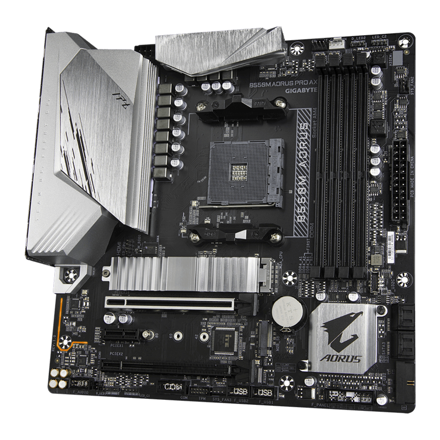
B550M AORUS PRO AX Motherboard Layout

Box Contents
- B550M AORUS PRO AX motherboard
- Two SATA cables
- User's Manual
- One antenna
* The box contents above are for reference only and the actual items shall depend on the product package you obtain.
The box contents are subject to change without notice.
Hardware Installation
Installation Precautions
The motherboard contains numerous delicate electronic circuits and components which can become damaged as a result of electrostatic discharge (ESD). Prior to installation, carefully read the user's manual and follow these procedures:
- Prior to installation, make sure the chassis is suitable for the motherboard.
- Prior to installation, do not remove or break motherboard S/N (Serial Number) sticker or warranty sticker provided by your dealer. These stickers are required for warranty validation.
- Always remove the AC power by unplugging the power cord from the power outlet before installing or removing the motherboard or other hardware components.
- When connecting hardware components to the internal connectors on the motherboard, make sure they are connected tightly and securely.
- When handling the motherboard, avoid touching any metal leads or connectors.
- It is best to wear an electrostatic discharge (ESD) wrist strap when handling electronic components such as a motherboard, CPU or memory. If you do not have an ESD wrist strap, keep your hands dry and first touch a metal object to eliminate static electricity.
- Prior to installing the motherboard, please have it on top of an antistatic pad or within an electrostatic shielding container.
- Before connecting or unplugging the power supply cable from the motherboard, make sure the power supply has been turned off.
- Before turning on the power, make sure the power supply voltage has been set according to the local voltage standard.
- Before using the product, please verify that all cables and power connectors of your hardware components are connected.
- To prevent damage to the motherboard, do not allow screws to come in contact with the motherboard circuit or its components.
- Make sure there are no leftover screws or metal components placed on the motherboard or within the computer casing.
- Do not place the computer system on an uneven surface.
- Do not place the computer system in a high-temperature or wet environment.
- Turning on the computer power during the installation process can lead to damage to system components as well as physical harm to the user.
- If you are uncertain about any installation steps or have a problem related to the use of the product, please consult a certified computer technician.
- If you use an adapter, extension power cable, or power strip, ensure to consult with its installation and/or grounding instructions.
Product Specifications
 CPU CPU |
|
 Chipset Chipset |
|
 Memory Memory |
|
 Onboard Graphics Onboard Graphics |
|
 Audio Audio |
|
 LAN LAN |
|
 Wireless Communication Module Wireless Communication Module |
|
 Expansion Slots Expansion Slots |
|
 Storage Interface Storage Interface |
|
 USB USB |
|
 Internal Connectors Internal Connectors |
|
 Back Panel Connectors Back Panel Connectors |
|
 Back Panel Connectors Back Panel Connectors |
|
 I/O Controller I/O Controller |
|
 Hardware Monitor Hardware Monitor |
|
 BIOS BIOS |
|
 Unique Features Unique Features |
|
 Bundled Software Bundled Software |
|
 Operating System Operating System |
|
 Form Factor Form Factor |
|
* GIGABYTE reserves the right to make any changes to the product specifications and product-related information without prior notice.

Please visit GIGABYTE's website for support lists of CPU, memory modules, SSDs, and M.2 devices.

Please visit the Support\Utility List page on GIGABYTE's website to download the latest version of apps.
Installing the CPU
 Read the following guidelines before you begin to install the CPU:
- Make sure that the motherboard supports the CPU.
(Go to GIGABYTE's website for the latest CPU support list.) - Always turn off the computer and unplug the power cord from the power outlet before installing the CPU to prevent hardware damage.
- Locate the pin one of the CPU. The CPU cannot be inserted if oriented incorrectly.
- Apply an even and thin layer of thermal grease on the surface of the CPU.
- Do not turn on the computer if the CPU cooler is not installed, otherwise overheating and damage of the CPU may occur.
- Set the CPU host frequency in accordance with the CPU specifications. It is not recommended that the system bus frequency be set beyond hardware specifications since it does not meet the standard requirements for the peripherals. If you wish to set the frequency beyond the standard specifications, please do so according to your hardware specifications including the CPU, graphics card, memory, hard drive, etc.
Installing the CPU
Completely lift up the CPU socket locking lever. Locate the pin one (denoted by a small triangle) of the CPU socket and the CPU. Once the CPU is positioned into its socket, place one finger down on the middle of the CPU, lowering the locking lever and latching it into the fully locked position.

Do not force the CPU into the CPU socket before the CPU socket locking lever is lifted up, or damage to the CPU and CPU socket may occur.
Installing the Memory
Read the following guidelines before you begin to install the memory:
- Make sure that the motherboard supports the memory. It is recommended that memory of the same capacity, brand, speed, and chips be used.
(Go to GIGABYTE's website for the latest supported memory speeds and memory modules.) - Always turn off the computer and unplug the power cord from the power outlet before installing the memory to prevent hardware damage.
- Memory modules have a foolproof design. A memory module can be installed in only one direction. If you are unable to insert the memory, switch the direction.
Dual Channel Memory Configuration
This motherboard provides four memory sockets and supports Dual Channel Technology. After the memory is installed, the BIOS will automatically detect the specifications and capacity of the memory. Enabling Dual Channel memory mode will double the original memory bandwidth.

Please visit GIGABYTE's website for details on hardware installation.
 Recommanded Dual Channel Memory Configuration:
| DDR4_A1 | DDR4_A2 | DDR4_B1 | DDR4_B2 | |
| 2 Modules | - - | DS/SS | - - | DS/SS |
| 4 Modules | DS/SS | DS/SS | DS/SS | DS/SS |
(SS=Single-Sided, DS=Double-Sided, "- -"=No Memory)
Due to CPU limitations, read the following guidelines before installing the memory in Dual Channel mode.
- Dual Channel mode cannot be enabled if only one memory module is installed.
- When enabling Dual Channel mode with two or four memory modules, it is recommended that memory of the same capacity, brand, speed, and chips be used.
Installing an Expansion Card
Read the following guidelines before you begin to install an expansion card:
- Make sure the motherboard supports the expansion card. Carefully read the manual that came with your expansion card.
- Always turn off the computer and unplug the power cord from the power outlet before installing an expansion card to prevent hardware damage.
Back Panel Connectors

- USB 2.0/1.1 Port
The USB port supports the USB 2.0/1.1 specification. Use this port for USB devices. - DisplayPort (Note 1)
DisplayPort delivers high quality digital imaging and audio, supporting bi-directional audio transmission. DisplayPort can support HDCP 2.3 content protection mechanisms. You can use this port to connect your DisplayPort-supported monitor. Note: The DisplayPort Technology can support a maximum resolution of 5120x2880@60 Hz but the actual resolutions supported depend on the monitor being used. - HDMI Port(Note 1)
![]()
The HDMI port is HDCP 2.3 compliant and supports Dolby TrueHD and DTS HD Master Audio formats. It also supports up to 192KHz/24bit 7.1-channel LPCM audio output. You can use this port to connect your HDMI-supported monitor. The maximum supported resolution is 4096x2160@60 Hz, but the actual resolutions supported are dependent on the monitor being used.
![]() After installing the DisplayPort/HDMI device, make sure to set the default sound playback device to DisplayPort/HDMI. (The item name may differ depending on your operating system.)
After installing the DisplayPort/HDMI device, make sure to set the default sound playback device to DisplayPort/HDMI. (The item name may differ depending on your operating system.) - USB 3.2 Gen 1 Port
The USB 3.2 Gen 1 port supports the USB 3.2 Gen 1 specification and is compatible to the USB 2.0 specification. Use this port for USB devices. - Q-Flash Plus Button (Note 2)
Q-Flash Plus allows you to update the BIOS when your system is off (S5 shutdown state). Save the latest BIOS on a USB thumb drive and plug it into the Q-Flash Plus port, and then you can now flash the BIOS automatically by simply pressing the Q-Flash Plus button. The QFLED will flash when the BIOS matching and flashing activities start and will stop flashing when the main BIOS flashing is complete.
(Note 1) For 3rd Generation AMD Ryzen™ with Radeon™ Graphics processors only.
(Note 2) To enable the Q-Flash Plus function please visit the "Unique Features" webpage of GIGABYTE's website. - USB 3.2 Gen 1 Port (Q-Flash Plus Port)
The USB 3.2 Gen 1 port supports the USB 3.2 Gen 1 specification and is compatible to the USB 2.0 specification. Use this port for USB devices. Before using Q-Flash Plus (Note 2), make sure to insert the USB flash drive into this port first. - RJ-45 LAN Port
The Gigabit Ethernet LAN port provides Internet connection at up to 2.5 Gbps data rate. The following describes the states of the LAN port LEDs.
![]()
Speed LED:
Activity LED:State Description Orange 2.5 Gbps data rate Green 1 Gbps data rate Off 100 Mbps data rate State Description Blinking Data transmission or receiving is occurring Off No data transmission or receiving is occurring


- USB 3.2 Gen 2 Type-A Port (Red)
The USB 3.2 Gen 2 port supports the USB 3.2 Gen 2 specification and is compatible to the USB 3.2 Gen 1 and USB 2.0 specification. Use this port for USB devices. - USB Type-C® Port
The reversible USB port supports the USB 3.2 Gen 2 specification and is compatible to the USB 3.2 Gen 1 and USB 2.0 specification. Use this port for USB devices. - SMA Antenna Connectors (2T2R)
Use this connector to connect an antenna.
![]() Tighten the antennas to the antenna connectors and then aim the antennas correctly for better signal reception.
Tighten the antennas to the antenna connectors and then aim the antennas correctly for better signal reception. - Center/Subwoofer Speaker Out
Use this audio jack to connect center/subwoofer speakers. - Rear Speaker Out
Use this audio jack to connect rear speakers. - Optical S/PDIF Out Connector
This connector provides digital audio out to an external audio system that supports digital optical audio. Before using this feature, ensure that your audio system provides an optical digital audio in connector. - Line In/Side Speaker Out
The line in jack. Use this audio jack for line in devices such as an optical drive, walkman, etc. - Line Out/Front Speaker Out
The line out jack. - Mic In/Side Speaker Out
The Mic in jack.
(Note 2) To enable the Q-Flash Plus function please visit the "Unique Features" webpage of GIGABYTE's website.
Audio Jack Configurations:
| Jack | Headphone/2-channel | 4-channel | 5.1-channel | 7.1-channel |
|  | | ||
| | | | |
| | |||
| | | | |
| |
 You can change the functionality of an audio jack using the audio software. If you want to install a Side Speaker, you need to retask either the Line in or Mic in jack to be Side Speaker out through the audio driver.
- When removing the cable connected to a back panel connector, first remove the cable from your device and then remove it from the motherboard.
- When removing the cable, pull it straight out from the connector. Do not rock it side to side to prevent an electrical short inside the cable connector.

Please visit GIGABYTE's website for details on configuring the audio software.
Internal Connectors

- ATX_12V
- ATX
- CPU_FAN
- SYS_FAN1/2/3
- CPU_OPT
- D_LED1/D_LED2
- LED_CPU
- LED_C1/LED_C2
- SATA3 0/1/2/3
- M2A_CPU/M2B_SB
- F_PANEL
- F_AUDIO
- F_U32C
- F_U32
- F_USB1/F_USB2
- TPM
- COM
- CLR_CMOS
- BAT
Read the following guidelines before connecting external devices:
- First make sure your devices are compliant with the connectors you wish to connect.
- Before installing the devices, be sure to turn off the devices and your computer. Unplug the power cord from the power outlet to prevent damage to the devices.
- After installing the device and before turning on the computer, make sure the device cable has been securely attached to the connector on the motherboard.
1/2) ATX_12V/ATX (2x4 12V Power Connector and 2x12 Main Power Connector)
With the use of the power connector, the power supply can supply enough stable power to all the components on the motherboard. Before connecting the power connector, first make sure the power supply is turned off and all devices are properly installed. The power connector possesses a foolproof design. Connect the power supply cable to the power connector in the correct orientation.
The 12V power connector mainly supplies power to the CPU. If the 12V power connector is not connected, the computer will not start.
To meet expansion requirements, it is recommended that a power supply that can withstand high power consumption be used (500W or greater). If a power supply is used that does not provide the required power, the result can lead to an unstable or unbootable system.

| Pin No. | Definition | Pin No. | Definition |
| 1 | GND (Only for 2x4-pin 12V) | 5 | +12V (Only for 2x4-pin 12V) |
| 2 | GND (Only for 2x4-pin 12V) | 6 | +12V (Only for 2x4-pin 12V) |
| 3 | GND | 7 | +12V |
| 4 | GND | 8 | +12V |

| Pin No. | Definition | Pin No. | Definition |
| 1 | 3.3V | 13 | 3.3V |
| 2 | 3.3V | 14 | -12V |
| 3 | GND | 15 | GND |
| 4 | +5V | 16 | PS_ON (soft On/Off) |
| 5 | GND | 17 | GND |
| 6 | +5V | 18 | GND |
| 7 | GND | 19 | GND |
| 8 | Power Good | 20 | NC |
| 9 | 5VSB (stand by +5V) | 21 | +5V |
| 10 | +12V | 22 | +5V |
| 11 | +12V (Only for 2x12-pin ATX) | 23 | +5V (Only for 2x12-pin ATX) |
| 12 | 3.3V (Only for 2x12-pin ATX) | 24 | GND (Only for 2x12-pin ATX) |
3/4) CPU_FAN/SYS_FAN1/2/3 (Fan Headers)
All fan headers on this motherboard are 4-pin. Most fan headers possess a foolproof insertion design. When connecting a fan cable, be sure to connect it in the correct orientation (the black connector wire is the ground wire). The speed control function requires the use of a fan with fan speed control design. For optimum heat dissipation, it is recommended that a system fan be installed inside the chassis.

| Pin No. | Definition |
| 1 | GND |
| 2 | Voltage Speed Control |
| 3 | Sense |
| 4 | PWM Speed Control |
| Connector | CPU_FAN | SYS_FAN1/2/3 |
| Maximum Current | 2A | 2A |
| Maximum Power | 24W | 24W |
- Be sure to connect fan cables to the fan headers to prevent your CPU and system from overheating. Overheating may result in damage to the CPU or the system may hang.
- These fan headers are not configuration jumper blocks. Do not place a jumper cap on the headers.
- CPU_OPT (Water Cooling CPU Fan Header)
The fan header is 4-pin and possesses a foolproof insertion design. Most fan headers possess a foolproof insertion design. When connecting a fan cable, be sure to connect it in the correct orientation (the black connector wire is the ground wire). The speed control function requires the use of a fan with fan speed control design.
![]()
Pin No. Definition 1 GND 2 Voltage Speed Control 3 Sense 4 PWM Speed Control

- Be sure to connect fan cables to the fan headers to prevent your CPU and system from overheating. Overheating may result in damage to the CPU or the system may hang.
- These fan headers are not configuration jumper blocks. Do not place a jumper cap on the headers.
- D_LED1/D_LED2 (Addressable LED Strip Headers)
The headers can be used to connect a standard 5050 addressable LED strip, with maximum power rating of 5A (5V) and maximum number of 1000 LEDs.
![]()
Pin No. Definition 1 V (5V) 2 Data 3 No Pin 4 GND Connect your addressable LED strip to the header. The power pin (marked with a triangle on the plug) of the LED strip must be connected to Pin 1 of the addressable LED strip header. Incorrect connection may lead to the damage of the LED strip.
![]()
- LED_CPU (CPU Cooler LED Strip/RGB LED Strip Header)
The header can be used to connect a CPU cooler LED strip or a standard 5050 RGB LED strip (12V/G/R/B), with maximum power rating of 2A (12V) and maximum length of 2m.
![]()
Connect the CPU cooler LED strip/RGB LED strip to the header. The RGB LED Strip power pin (marked with a triangle on the plug) of the LED strip must be connected to Pin 1 (12V) of this header. Incorrect connection may lead to the damage of the LED strip.Pin No. Definition 1 12V 2 G 3 R 4 B
![]()
![]() For how to turn on/off the lights of the LED strip please visit the "Unique Features" webpage of GIGABYTE's website.
For how to turn on/off the lights of the LED strip please visit the "Unique Features" webpage of GIGABYTE's website.
![caution]() Before installing the devices, be sure to turn off the devices and your computer. Unplug the power cord from the power outlet to prevent damage to the devices.
Before installing the devices, be sure to turn off the devices and your computer. Unplug the power cord from the power outlet to prevent damage to the devices. - LED_C1/LED_C2 (RGB LED Strip Headers)
The headers can be used to connect a standard 5050 RGB LED strip (12V/G/R/B), with maximum power rating of 2A (12V) and maximum length of 2m.
![]()
Connect the CPU cooler LED strip/RGB LED strip to the header. The RGB LED power pin (marked with a triangle on the plug) of the LED strip must Strip be connected to Pin 1 (12V) of this header. Incorrect connection may lead to the damage of the LED strip.Pin No. Definition 1 12V 2 G 3 R 4 B
![]()
![]() For how to turn on/off the lights of the LED strip please visit the "Unique Features" webpage of GIGABYTE's website.
For how to turn on/off the lights of the LED strip please visit the "Unique Features" webpage of GIGABYTE's website.
![caution]() Before installing the devices, be sure to turn off the devices and your computer. Unplug the power cord from the power outlet to prevent damage to the devices.
Before installing the devices, be sure to turn off the devices and your computer. Unplug the power cord from the power outlet to prevent damage to the devices. - SATA3 0/1/2/3 (SATA 6Gb/s Connectors)
The SATA connectors conform to SATA 6Gb/s standard and are compatible with SATA 3Gb/s and SATA 1.5Gb/s standard. Each SATA connector supports a single SATA device. The SATA connectors support RAID 0, RAID 1, and RAID 10. Refer to Chapter "Configuring a RAID Set," for instructions on configuring a RAID array.
![]()
Pin No. Definition 1 GND 2 TXP 3 TXN 4 GND 5 RXN 6 RXP 7 GND - 2A_CPU/M2B_SB (M.2 Socket 3 Connectors)
The M.2 connectors support M.2 SATA SSDs or M.2 PCIe SSDs and support RAID configuration. Please note that an M.2 PCIe SSD cannot be used to create a RAID set either with an M.2 SATA SSD or a SATA hard drive. Refer to Chapter "Configuring a RAID Set," for instructions on configuring a RAID array.
")
Follow the steps below to correctly install an M.2 SSD in the M.2 connector.
Step 1:
Locate the M.2 connector where you will install the M.2 SSD, use a screwdriver to unfasten the screw on the heatsink and then remove the heatsink. (Only the M2A_CPU connector has the heatsink)
Step 2:
Locate the proper mounting hole based on the length of your M.2 SSD drive. If needed, move the standoff to the desired mounting hole. Insert the M.2 SSD into the M.2 connector at an angle.
Step 3:
Press the M.2 SSD down and then secure it with the screw. Replace the heatsink and secure it to the original hole. Remove the protective film from the bottom of the heatsink before replacing the heatsink. - F_PANEL (Front Panel Header)
Connect the power switch, reset switch, speaker, chassis intrusion switch/sensor and system status indicator on the chassis to this header according to the pin assignments below. Note the positive and negative pins before connecting the cables.
![]()


")

- PLED/PWR_LED (Power LED):
Connects to the power status indicator on the chassis front panel. The LED is on when the system is operating. The LED is off when the system is in S3/S4 sleep state or powered off (S5). - PW (Power Switch):
Connects to the power switch on the chassis front panel. You may configure the way to turn off your system using the power switch (refer to Chapter "BIOS Setup," "Settings\Platform Power," for more information). - SPEAK (Speaker):
Connects to the speaker on the chassis front panel. The system reports system startup status by issuing a beep code. One single short beep will be heard if no problem is detected at system startup. - HD (Hard Drive Activity LED):Connects to the hard drive activity LED on the chassis front panel. The LED is on when the hard drive is reading or writing data.
- RES (Reset Switch):
Connects to the reset switch on the chassis front panel. Press the reset switch to restart the computer if the computer freezes and fails to perform a normal restart. - CI (Chassis Intrusion Header):
Connects to the chassis intrusion switch/sensor on the chassis that can detect if the chassis cover has been removed. This function requires a chassis with a chassis intrusion switch/sensor. - NC: No connection.
![]() The front panel design may differ by chassis. A front panel module mainly consists of power switch, reset switch, power LED, hard drive activity LED, speaker and etc. When connecting your chassis front panel module to this header, make sure the wire assignments and the pin assignments are matched correctly.
The front panel design may differ by chassis. A front panel module mainly consists of power switch, reset switch, power LED, hard drive activity LED, speaker and etc. When connecting your chassis front panel module to this header, make sure the wire assignments and the pin assignments are matched correctly.
- F_AUDIO (Front Panel Audio Header)
The front panel audio header supports High Definition audio (HD). You may connect your chassis front panel audio module to this header. Make sure the wire assignments of the module connector match the pin assignments of the motherboard header. Incorrect connection between the module connector and the motherboard header will make the device unable to work or even damage it.
![]()
Pin No. Definition Pin No. Definition 1 MIC2_L 6 Sense F_ 2 GND 7 FAUDIO_JD 3 MIC2_R 8 No Pin 4 NC 9 LINE2_L 5 LINE2_R 10 Sense ![]() Some chassis provide a front panel audio module that has separated connectors on each wire instead of a single plug. For information about connecting the front panel audio module that has different wire assignments, please contact the chassis manufacturer.
Some chassis provide a front panel audio module that has separated connectors on each wire instead of a single plug. For information about connecting the front panel audio module that has different wire assignments, please contact the chassis manufacturer. - F_U32C (USB Type-C® Header with USB 3.2 Gen 1 Support)
The header conforms to USB 3.2 Gen 1 specification and can provide one USB port.
![]()
Pin No. Definition Pin No. Definition Pin No. Definition 1 VBUS 8 CC1 15 RX2+ 2 TX1+ 9 SBU1 16 RX2- 3 TX1- 10 SBU2 17 GND 4 GND 11 VBUS 18 D- 5 RX1+ 12 TX2+ 19 D+ 6 RX1- 13 TX2- 20 CC2 7 VBUS 14 GND - F_U32 (USB 3.2 Gen 1 Header)
The header conforms to USB 3.2 Gen 1 and USB 2.0 specification and can provide two USB ports. For purchasing the optional 3.5" front panel that provides two USB 3.2 Gen 1 ports, please contact the local dealer.
![]()
Pin No. Definition Pin No. Definition Pin No. Definition 1 VBUS 8 D1- 15 SSTX2- 2 SSRX1- 9 D1+ 16 GND 3 SSRX1+ 10 NC 17 SSRX2+ 4 GND 11 D2+ 18 SSRX2- 5 SSTX1- 12 D2- 19 VBUS 6 SSTX1+ 13 GND 20 No Pin 7 GND 14 SSTX2+ - F_USB1/F_USB2 (USB 2.0/1.1 Headers)
The headers conform to USB 2.0/1.1 specification. Each USB header can provide two USB ports via an optional USB bracket. For purchasing the optional USB bracket, please contact the local dealer.
![]()
Pin No. Definition Pin No. Definition 1 Power (5V) 6 USB DY+ 2 Power (5V) 7 GND 3 USB DX- 8 GND 4 USB DY- 9 No Pin 5 USB DX+ 10 NC ![caution]()
- Do not plug the IEEE 1394 bracket (2x5-pin) cable into the USB 2.0/1.1 header.
- Prior to installing the USB bracket, be sure to turn off your computer and unplug the power cord from the power outlet to prevent damage to the USB bracket.
- TPM (Trusted Platform Module Header)
You may connect a TPM (Trusted Platform Module) to this header.
![]()
Pin No. Definition Pin No. Definition 1 LAD0 7 LAD3 2 VCC3 8 GND _ F 3 LAD1 9 LFRAME 4 No Pin 10 NC 5 LAD2 11 SERIRQ 6 LCLK 12 LRESET - COM (Serial Port Header)
The COM header can provide one serial port via an optional COM port cable. For purchasing the optional COM port cable, please contact the local dealer.
![]()
Pin No. Definition Pin No. Definition 1 NDCD- 6 NDSR- 2 NSIN 7 NRTS- 3 NSOUT 8 NCTS- 4 NDTR- 9 NRI- 5 GND 10 _3 No Pin U - CLR_CMOS (Clear CMOS Jumper)
Use this jumper to clear the BIOS configuration and reset the CMOS values to factory defaults. To clear the CMOS values, use a metal object like a screwdriver to touch the two pins for a few seconds.![]()
Open: Normal ![]()
Short: Clear CMOS Values ![caution]()
- Always turn off your computer before clearing the CMOS values.
- After system restart, go to BIOS Setup to load factory defaults (select Load Optimized Defaults) or manually configure the BIOS settings (refer to Chapter "BIOS Setup," for BIOS configurations).
- BAT (Battery)
The battery provides power to keep the values (such as BIOS configurations, date, and time information) in the CMOS when the computer is turned off. Replace the battery when the battery voltage drops to a low level, or the CMOS values may not be accurate or may be lost.
![]()
You may clear the CMOS values by removing the battery:- Turn off your computer and unplug the power cord.
- Gently remove the battery from the battery holder and wait for one minute. (Or use a metal object like a screwdriver to touch the positive and negative terminals of the battery holder, making them short for 5 seconds.)
- Replace the battery.
- Plug in the power cord and restart your computer.
![caution]()
- Always turn off your computer and unplug the power cord before replacing the battery.
- Replace the battery with an equivalent one. Damage to your devices may occur if the battery is replaced with an incorrect model.
- Contact the place of purchase or local dealer if you are not able to replace the battery by yourself or uncertain about the battery model.
- When installing the battery, note the orientation of the positive side (+) and the negative side (-) of the battery (the positive side should face up).
- Used batteries must be handled in accordancewith local environmental regulations.


BIOS Setup
BIOS (Basic Input and Output System) records hardware parameters of the system in the CMOS on the motherboard. Its major functions include conducting the Power-On Self-Test (POST) during system startup, saving system parameters and loading operating system, etc. BIOS includes a BIOS Setup program that allows the user to modify basic system configuration settings or to activate certain system features.
When the power is turned off, the battery on the motherboard supplies the necessary power to the CMOS to keep the configuration values in the CMOS.
To access the BIOS Setup program, press the <Delete> key during the POST when the power is turned on.
To upgrade the BIOS, use either the GIGABYTE Q-Flash or @BIOS utility.
- Q-Flash allows the user to quickly and easily upgrade or back up BIOS without entering the operating system.
- @BIOS is a Windows-based utility that searches and downloads the latest version of BIOS from the Internet and updates the BIOS.
- Because BIOS flashing is potentially risky, if you do not encounter problems using the current version of BIOS, it is recommended that you not flash the BIOS. To flash the BIOS, do it with caution. Inadequate BIOS flashing may result in system malfunction.
- It is recommended that you not alter the default settings (unless you need to) to prevent system instability or other unexpected results. Inadequately altering the settings may result in system's failure to boot. If this occurs, try to clear the CMOS values and reset the board to default values. (Refer to the "Load Optimized Defaults" section in this chapter or introductions of the battery/clear CMOS jumper in Chapter Hardware Installation for how to clear the CMOS values.)
Startup Screen
The following startup Logo screen will appear when the computer boots.

There are two different BIOS modes as follows and you can use the <F2> key to switch between the two modes. Easy Mode allows users to quickly view their current system information or to make adjustments for optimum performance. In Easy Mode, you can use your mouse to move through configuration items. The Advanced Mode provides detailed BIOS settings. You can press the arrow keys on your keyboard to move among the items and press <Enter> to accept or enter a sub-menu. Or you can use your mouse to select the item you want.
- When the system is not stable as usual, select the Load Optimized Defaults item to set your system to its defaults.
- The BIOS Setup menus described in this chapter are for reference only and may differ by BIOS version.
The Main Menu

Advanced Mode Function Keys
< >< >< > > | Move the selection bar to select a setup menu |
< >< >< > > | Move the selection bar to select an configuration item on a menu |
| <Enter>/Double Click | Execute command or enter a menu |
| <+>/<Page Up> | Increase the numeric value or make changes |
| <->/<Page Down> | Decrease the numeric value or make changes |
| <F1> | Show descriptions of the function keys |
| <F2> | Switch to Easy Mode |
| <F3> | Save the current BIOS settings to a profile |
| <F4> | Load the BIOS settings from a profile created before |
| <F5> | Restore the previous BIOS settings for the current submenus |
| <F6> | Display the Smart Fan 5 screen |
| <F7> | Load the Optimized BIOS default settings for the current submenus |
| <F8> | Access the Q-Flash utility |
| <F10> | Save all the changes and exit the BIOS Setup program |
| <F11> | Switch to the Favorites submenu |
| <F12> | Capture the current screen as an image and save it to your USB drive |
| <Insert> | Add or remove a favorite option |
| <Ctrl>+<S> | Display information on the installed memory |
| <Esc> | Main Menu: Exit the BIOS Setup program Submenus: Exit current submenu |
Favorites (F11)
")
Set your frequently used options as your favorites and use the <F11> key to quickly switch to the page where all of your favorite options are located. To add or remove a favorite option, go to its original page and press <Insert> on the option. The option is marked with a star sign if set as a "favorite."
Tweaker

Whether the system will work stably with the overclock/overvoltage settings you made is dependent on your overall system configurations. Incorrectly doing overclock/overvoltage may result in damage to CPU, chipset, or memory and reduce the useful life of these components. This page is for advanced users only and we recommend you not to alter the default settings to prevent system instability or other unexpected results. (Inadequately altering the settings may result in system's failure to boot. If this occurs, clear the CMOS values and reset the board to default values.)
 CPU Clock Control
Allows you to manually set the CPU base clock in 1 MHz increments. (Default: Auto)

It is highly recommended that the CPU frequency be set in accordance with the CPU specifications.
Spread Spectrum Control
Enables or disables CPU/PCIe Spread Spectrum. (Default: Auto)
CPU Ratio Mode (Note)
Allows you to set the core ratio for all CPU cores or individual cores. (Default: All cores)
CCD0 CCX0/1 Ratio (Note)
Allows you to manually set the core ratio for the CPU CCX0, 1 cores. This item is configurable only when CPU Ratio Mode is set to Per CCX. (Default: Auto)
CPU Clock Ratio
Allows you to alter the clock ratio for the installed CPU. The adjustable range is dependent on the CPU being installed.
GFX Clock Frequency (Note)
Allows you to alter the frequency for the GPU. After you alter the GFX Clock Frequency settings, make sure to adjust the GFX Core Voltage settings. (Default: Auto)
NOTE: The adjustable range is dependent on the CPU being installed. Auto lets the BIOS automatically configure this setting.
GFX Core Voltage (Note)
Allows you to alter the voltage for the GPU. (Default: Auto)
NOTE: The adjustable range is dependent on the CPU being installed. Auto lets the BIOS automatically configure this setting.
Advanced CPU Settings
& Core Performance Boost (Note)
Allows you to determine whether to enable the Core Performance Boost (CPB) technology, a CPU performance-boost technology. (Default: Auto)
(Note) This item is present only when you install a CPU that supports this feature.
SVM Mode
Virtualization enhanced by Virtualization Technology will allow a platform to run multiple operating systems and applications in independent partitions. With virtualization, one computer system can function as multiple virtual systems. (Default: Disabled)
AMD Cool&Quiet function
| Enabled | Lets the AMD Cool'n'Quiet driver dynamically adjust the CPU clock and VID to reduce heat output from your computer and its power consumption. (Default) |
| Disabled | Disables this function. |
PPC Adjustment (Note 1)
Allows you to fix the PState of the CPU. (Default: PState 0)
Global C-state Control (Note 1)
Allows you to determine whether to let the CPU enter C states. When enabled, the CPU core frequency will be reduced during system halt state to decrease power consumption. (Default: Auto)
Power Supply Idle Control (Note 1)
Enables or disables Package C6 State.
| Typical Current Idle | Disables this function. |
| Low Current Idle | Enables this function. |
| Auto | Lets the BIOS automatically configure this setting. (Default) |
CCD Control (Note 1)
Sets the number of CCDs to be used. (Default: Auto)
Downcore Control
Allows you to select the number of CPU cores to enable (the number of CPU cores may vary by CPU). (Default: Auto)
SMT Mode
Allows you to enable or disable the CPU Simultaneous Multi-Threading technology. (Default: Auto)
CPPC (Note 1)
Enables or disables the CPPC feature. (Default: Auto)
CPPC Preferred Cores (Note 1)
Enables or disables the CPPC Preferred Cores feature. (Default: Auto)
Extreme Memory Profile (X.M.P.) (Note 2)
Allows the BIOS to read the SPD data on XMP memory module(s) to enhance memory performance when enabled.
| Disabled | Disables this function. (Default) |
| Profile1 | Uses Profile 1 settings. |
| Profile2 (Note 2) | Uses Profile 2 settings. |
XMP High Frequency Support (Note 2)
Allows you to select the compatibility level for high-frequency memory. This item is configurable only when Extreme Memory Profile (X.M.P.) is set to Profile1 or Profile2. (Default: Auto)
System Memory Multiplier
Allows you to set the system memory multiplier. Auto sets memory multiplier according to memory SPD data. (Default: Auto)
(Note 1) This item is present only when you install a CPU that supports this feature.
(Note 2) This item is present only when you install a CPU and a memory module that support this feature.
- Advanced Memory Settings ƒ
- Memory Subtimings
![]() Standard Timing Control, Advanced Timing Control, CAD Bus Setup Timing, CAD Bus
Standard Timing Control, Advanced Timing Control, CAD Bus Setup Timing, CAD Bus
Drive Strength, Data Bus Configuration
These sections provide memory timing settings. Note: Your system may become unstable or fail to boot after you make changes on the memory timings. If this occurs, please reset the board to default values by loading optimized defaults or clearing the CMOS values. - ƒ SPD Info
Displays information on the installed memory.
 Standard Timing Control, Advanced Timing Control, CAD Bus Setup Timing, CAD Bus
 CPU Vcore/Dynamic Vcore(DVID)/VCORE SOC/Dynamic VCORE SOC(DVID)/CPU VDD18/CPU VDDP/A_VDD18S5/DRAM Voltage (CH A/B)/DDRVPP Voltage (CH A/B)/ DRAM Termination (CH A/B)
These items allow you to adjust the CPU Vcore and memory voltages.
- ƒ CPU/VRM Settings
This submenu allows you to configure Load-Line Calibration level, over-voltage protection level, over-current protection level, and PWM phases.
Settings

- Platform Power
![]() AC BACK
AC BACK
Determines the state of the system after the return of power from an AC power loss.![]() Memory
MemoryThe system returns to its last known awake state upon the return of the AC power. ![]() Always On
Always OnThe system is turned on upon the return of the AC power. ![]() Always Off
Always OffThe system stays off upon the return of the AC power. (Default)
ErP
Determines whether to let the system consume least power in S5 (shutdown) state. (Default: Disabled) Note: When this item is set to Enabled, the Resume by Alarm function becomes unavailable.
Soft-Off by PWR-BTTN
Configures the way to turn off the computer in MS-DOS mode using the power button.
| Instant-Off | Press the power button and then the system will be turned off instantly. (Default) |
| Delay 4 Sec. | Press and hold the power button for 4 seconds to turn off the system. If the power button is pressed for less than 4 seconds, the system will enter suspend mode. |
Power Loading
Enables or disables dummy load. When the power supply is at low load, a self-protection will activate causing it to shutdown or fail. If this occurs, please set to Enabled. Auto lets the BIOS automatically configure this setting. (Default: Auto)
Resume by Alarm
Determines whether to power on the system at a desired time. (Default: Disabled)
If enabled, set the date and time as following:
Wake up day: Turn on the system at a specific time on each day or on a specific day in a month.
Wake up hour/minute/second: Set the time at which the system will be powered on automatically.
Note: When using this function, avoid inadequate shutdown from the operating system or removal of the AC power, or the settings may not be effective.
Wake on LAN
Enables or disables the wake on LAN function. (Default: Enabled)
High Precision Event Timer
Enables or disables High Precision Event Timer (HPET) in the operating system. (Default: Enabled)
CEC 2019 Ready
Allows you to select whether to allow the system to adjust power consumption when it is in shutdown, idle, or standby state in order to comply with the CEC (California Energy Commission) 2019 Standards. (Default: Disabled)
- IO Ports
![]() Initial Display Output
Initial Display Output
Specifies the first initiation of the monitor display from the installed PCI Express graphics card or the onboard graphics.![]() IGD Video (Note)
IGD Video (Note)Sets the onboard graphics as the first display. ![]() PCIe 1 Slot
PCIe 1 SlotSets the graphics card on the PCIEX16 slot as the first display. (Default) ![]() PCIe 2 Slot
PCIe 2 SlotSets the graphics card on the PCIEX2 slot as the first display.
Integrated Graphics (Note)
Enables or disables the onboard graphics function.
| Auto | The BIOS will automatically enable or disable the onboard graphics depending on the graphics card being installed. (Default) |
| Forces | Enables the onboard graphics. |
| Disabled | Disables the onboard graphics. |
UMA Mode (Note)
Specify the UMA mode.
| Auto | Lets the BIOS automatically configure this setting. (Default) |
| UMA Specified | Sets the UMA Frame Buffer Size. |
| UMA Auto | Sets the display resolution. |
| UMA Game Optimized | Adjusts the frame buffer size based on the total system memory size. |
This item is configurable only when Integrated Graphics is set to Forces.
UMA Frame Buffer Size (Note)
Frame buffer size is the total amount of system memory allocated solely for the onboard graphics controller. MS-DOS, for example, will use only this memory for display. Options are: Auto (default), 64M~2G. This item is configurable only when UMA Mode is set to UMA Specified.
Display Resolution (Note)
Allows you to set the display resolution. Options are: Auto (default), 1920x1080 and below, 2560x1600, 3840x2160.
This item is configurable only when UMA Mode is set to UMA Auto.
HD Audio Controller
Enables or disables the onboard audio function. (Default: Enabled)
If you wish to install a 3rd party add-in audio card instead of using the onboard audio, set this item to Disabled.
PCIEX16 Bifurcation
Allows you to determine how the bandwidth of the PCIEX16 slot is divided. Options: Auto, PCIE 2x8, PCIE 1x8/2x4, PCIE 2x4/1x8, PCIE 4x4 (Note). (Default: Auto)
Above 4G Decoding
Enables or disables 64-bit capable devices to be decoded in above 4 GB address space (only if your system supports 64-bit PCI decoding). Set to Enabled if more than one advanced graphics card are installed and their drivers are not able to be launched when entering the operating system (because of the limited 4 GB memory address space). (Default: Disabled)
Re-Size BAR Support
Enables or disables support for Resizable BAR. (Default: Disabled)
Onboard LAN Controller
Enables or disables the onboard LAN function. (Default: Enabled)
If you wish to install a 3rd party add-in network card instead of using the onboard LAN, set this item to Disabled.
(Note) This item is present only when you install a CPU that supports this feature.
- Super IO Configuration
![]() Serial Port
Serial Port
Enables or disables the onboard serial port. (Default: Enabled) - USB Configuration & Legacy USB Support
Allows USB keyboard/mouse to be used in MS-DOS. (Default: Enabled)
![]() XHCI Hand-off
XHCI Hand-off
Determines whether to enable XHCI Hand-off feature for an operating system without XHCI Hand-off support. (Default: Enabled)
![]() USB Mass Storage Driver Support
USB Mass Storage Driver Support
Enables or disables support for USB storage devices. (Default: Enabled)
![]() Port 60/64 Emulation
Port 60/64 Emulation
Enables or disables emulation of I/O ports 64h and 60h. This should be enabled for full legacy support for USB keyboards/mice in MS-DOS or in operating system that does not natively support USB devices. (Default: Disabled)
![]() Mass Storage Devices
Mass Storage Devices
Displays a list of connected USB mass storage devices. This item appears only when a USB storage device is installed. - NVMe Configuration
Displays information on your M.2 NVME PCIe SSD if installed. - SATA Configuration
![]() SATA Mode
SATA Mode
Enables or disables RAID for the SATA controllers integrated in the Chipset or configures the SATA controllers to AHCI mode.![]() RAID
RAIDEnables RAID for the SATA controller. ![]() AHCI
AHCIConfigures the SATA controllers to AHCI mode. Advanced Host Controller Interface (AHCI) is an interface specification that allows the storage driver to enable advanced Serial ATA features such as Native Command Queuing and hot plug. (Default)
NVMe RAID mode
Allows you to determine whether to use your M.2 NVMe PCIe SSDs to configure RAID. (Default: Disabled)
Chipset SATA Port Enable
Enables or disables the integrated SATA controllers. (Default: Enabled)
Chipset SATA Port 0/1/2/3
Displays the information of the connected SATA device(s).
- Network Stack Configuration
![]() Network Stack
Network Stack
Disables or enables booting from the network to install a GPT format OS, such as installing the OS from the Windows Deployment Services server. (Default: Disabled)
![]() IPv4 PXE Support
IPv4 PXE Support
Enables or disables IPv4 PXE Support. This item is configurable only when Network Stack is enabled.
![]() IPv4 HTTP Support
IPv4 HTTP Support
Enables or disables HTTP boot support for IPv4. This item is configurable only when Network Stack is enabled.
![]() IPv6 PXE Support
IPv6 PXE Support
Enables or disables IPv6 PXE Support. This item is configurable only when Network Stack is enabled.
![]() IPv6 HTTP Support
IPv6 HTTP Support
Enables or disables HTTP boot support for IPv6. This item is configurable only when Network Stack is enabled.
![]() PXE boot wait time
PXE boot wait time
Allows you to configure how long to wait before you can press <Esc> to abort the PXE boot. This item is configurable only when Network Stack is enabled. (Default: 0)
![]() Media detect count
Media detect count
Allows you to set the number of times to check the presence of media. This item is configurable only when Network Stack is enabled. (Default: 1) - Realtek PCIe Family Controller
This sub-menu provides information on LAN configuration and related configuration options. - Miscellaneous
![]() LEDs in System Power On State
LEDs in System Power On State
Allows you to enable or disable motherboard LED lighting when the system is on.![]() Off
OffDisables the selected lighting mode when the system is on. ![]() On
OnEnables the selected lighting mode when the system is on. (Default) ![]() LEDs in Sleep, Hibernation, and Soft Off States
LEDs in Sleep, Hibernation, and Soft Off States
Allows you to set the lighting mode of the motherboard LEDs in system S3/S4/S5 state. This item is configurable when LEDs in System Power On State is set to On.![]() Off
OffDisables the selected lighting mode when the system enters S3/S4/S5 state. (Default) ![]() On
OnEnables the selected lighting mode when the system enters S3/S4/S5 state. ![]() PCIe Slot Configuration
PCIe Slot Configuration
Allows you to set the operation mode of the PCI Express slots to Gen 1, Gen 2, Gen 3, or Gen 4 (Note). Actual operation mode is subject to the hardware specification of each slot. Auto lets the BIOS automatically configure this setting. (Default: Auto)
![]() PCIe ASPM Mode
PCIe ASPM Mode
Allows you to configure the ASPM mode for the device connected to the CPU PCI Express bus. (Default: Disabled)
![]() 3DMark01 Enhancement
3DMark01 Enhancement
Allows you to determine whether to enhance some legacy benchmark performance. (Default: Disabled)
![]() IOMMU
IOMMU
Enables or disables AMD IOMMU support. (Default: Auto)
![]() AMD CPU fTPM
AMD CPU fTPM
Enables or disables the TPM 2.0 function integrated in the AMD CPU. (Default: Disabled) - Trusted Computing
Enables or disables Trusted Platform Module (TPM). - AMD CBS
This sub-menu provides AMD CBS-related configuration options. - PC Health
![]() Reset Case Open Status
Reset Case Open Status ![]() Disabled
DisabledKeeps or clears the record of previous chassis intrusion status. (Default) ![]() Enabled
EnabledClears the record of previous chassis intrusion status and the Case Open field will show "No" at next boot. (Note) This item is present only when you install a CPU that supports this feature.
![]() Case Open
Case Open
Displays the detection status of the chassis intrusion detection device attached to the motherboard CI header. If the system chassis cover is removed, this field will show "Yes", otherwise it will show "No". To clear the chassis intrusion status record, set Reset Case Open Status to Enabled, save the settings to the CMOS, and then restart your system.
![]() CPU Vcore/CPU VDDP/DRAM Channel A/B Voltage/+3.3V/+5V/CHIPSET Core/+12V/ VCORE SOC
CPU Vcore/CPU VDDP/DRAM Channel A/B Voltage/+3.3V/+5V/CHIPSET Core/+12V/ VCORE SOC
Displays the current system voltages. - Smart Fan 5
![]() Monitor
Monitor
Allows you to select a target to monitor and to make further adjustment. (Default: CPU FAN)
![]() Fan Speed Control
Fan Speed Control
Allows you to determine whether to enable the fan speed control function and adjust the fan speed.![]() Normal
NormalAllows the fan to run at different speeds according to the temperature. You can adjust the fan speed with System Information Viewer based on your system requirements. (Default) ![]() Silent
SilentAllows the fan to run at slow speeds. ![]() Manual
ManualAllows you to control the fan speed in the curve graph. ![]() Full Speed
Full SpeedAllows the fan to run at full speeds. ![]() Fan Control Use Temperature Input
Fan Control Use Temperature Input
Allows you to select the reference temperature for fan speed control.
![]() Temperature Interval
Temperature Interval
Allows you to select the temperature interval for fan speed change.
![]() Fan Control Mode
Fan Control Mode![]() Auto
AutoLets the BIOS automatically detect the type of fan installed and sets the optimal control mode. (Default) ![]() Voltage
VoltageVoltage mode is recommended for a 3-pin fan. ![]() PWM
PWMPWM mode is recommended for a 4-pin fan. ![]() Fan Stop
Fan Stop
Enables or disables the fan stop function. You can set the temperature limit using the temperature curve. The fan stops operation when the temperature is lower than the limit. (Default: Disabled)
![]() Temperature
Temperature
Displays the current temperature of the selected target area.
![]() Fan Speed
Fan Speed
Displays current fan speeds.
![]() Flow Rate
Flow Rate
Displays the flow rate of your water cooling system.
![]() Temperature Warning Control
Temperature Warning Control
Sets the warning threshold for temperature. When temperature exceeds the threshold, BIOS will emit warning sound. Options are: Disabled (default), 60oC/140oF, 70oC/158oF, 80oC/176oF, 90oC/194oF.
![]() Fan Fail Warning
Fan Fail Warning
Allows the system to emit warning sound if the fan is not connected or fails. Check the fan condition or fan connection when this occurs. (Default: Disabled)
System Info

This section provides information on your motherboard model and BIOS version. You can also select the default language used by the BIOS and manually set the system time.
System Language
Selects the default language used by the BIOS.
System Date
Sets the system date. The date format is week (read-only), month, date, and year. Use <Enter> to switch between the Month, Date, and Year fields and use the <Page Up> or <Page Down> key to set the desired value.
System Time
Sets the system time. The time format is hour, minute, and second. For example, 1 p.m. is 13:00:00. Use <Enter> to switch between the Hour, Minute, and Second fields and use the <Page Up> or <Page Down> key to set the desired value.
Access Level
Displays the current access level depending on the type of password protection used. (If no password is set, the default will display as Administrator.) The Administrator level allows you to make changes to all BIOS settings; the User level only allows you to make changes to certain BIOS settings but not all.
- Plug in Devices Info
Displays information on your SATA, PCI Express, and M.2 devices if installed. - Q-Flash
Allows you to access the Q-Flash utility to update the BIOS or back up the current BIOS configuration.
Boot

Boot Option Priorities
Specifies the overall boot order from the available devices. Removable storage devices that support GPT format will be prefixed with "UEFI:" string on the boot device list. To boot from an operating system that supports GPT partitioning, select the device prefixed with "UEFI:" string.
Or if you want to install an operating system that supports GPT partitioning such as Windows 10 64-bit, select the optical drive that contains the Windows 10 64-bit installation disc and is prefixed with "UEFI:" string.
Bootup NumLock State
Enables or disables Numlock feature on the numeric keypad of the keyboard after the POST. (Default: On)
Security Option
Specifies whether a password is required every time the system boots, or only when you enter BIOS Setup. After configuring this item, set the password(s) under the Administrator Password/User Password item.
| Setup | A password is only required for entering the BIOS Setup program. |
| System | A password is required for booting the system and for entering the BIOS Setup program. (Default) |
Full Screen LOGO Show
Allows you to determine whether to display the GIGABYTE Logo at system startup. Disabled skips the GIGABYTE Logo when the system starts up. (Default: Enabled)
Fast Boot
Enables or disables Fast Boot to shorten the OS boot process. Ultra Fast provides the fastest bootup speed. (Default: Disabled)
SATA Support
| Last Boot SATA Devices Only | Except for the previous boot drive, all SATA devices are disabled before the OS boot process completes. (Default) |
| All SATA Devices | All SATA devices are functional in the operating system and during the POST. |
This item is configurable only when Fast Boot is set to Enabled or Ultra Fast.
NVMe Support
Allows you to enable or disable NVMe device(s). (Default: Enabled)
This item is configurable only when Fast Boot is set to Enabled or Ultra Fast.
VGA Support
Allows you to select which type of operating system to boot.
| Auto | Enables legacy option ROM only. |
| EFI Driver | Enables EFI option ROM. (Default) |
This item is configurable only when Fast Boot is set to Enabled or Ultra Fast.
USB Support
| Disabled | All USB devices are disabled before the OS boot process completes. |
| Full Initial | All USB devices are functional in the operating system and during the POST. (Default) |
| Partial Initial | Part of the USB devices are disabled before the OS boot process completes. |
This item is configurable only when Fast Boot is set to Enabled. This function is disabled when Fast Boot is set to Ultra Fast.
NetWork Stack Driver Support
| Disabled | Disables booting from the network. (Default) |
| Enabled | Enables booting from the network. |
This item is configurable only when Fast Boot is set to Enabled or Ultra Fast.
CSM Support
Enables or disables UEFI CSM (Compatibility Support Module) to support a legacy PC boot process.
| Disabled | Disables UEFI CSM and supports UEFI BIOS boot process only. |
| Enabled | Enables UEFI CSM. (Default) |
LAN PXE Boot Option ROM
Allows you to select whether to enable the legacy option ROM for the LAN controller. (Default: Disabled) This item is configurable only when CSM Support is set to Enabled.
Storage Boot Option Control
Allows you to select whether to enable the UEFI or legacy option ROM for the storage device controller.
| Disabled | Disables option ROM. |
| UEFI Only | Enables UEFI option ROM only. (Default) |
| Legacy Only | Enables legacy option ROM only. |
This item is configurable only when CSM Support is set to Enabled.
Other PCI Device ROM Priority
Allows you to select whether to enable the UEFI or Legacy option ROM for the PCI device controller other than the LAN, storage device, and graphics controllers.
| Disabled | Disables option ROM. |
| UEFI Only | Enables UEFI option ROM only. (Default) |
| Legacy Only | Enables legacy option ROM only. |
This item is configurable only when CSM Support is set to Enabled.
Administrator Password
Allows you to configure an administrator password. Press <Enter> on this item, type the password, and then press <Enter>. You will be requested to confirm the password. Type the password again and press <Enter>. You must enter the administrator password (or user password) at system startup and when entering BIOS Setup. Differing from the user password, the administrator password allows you to make changes to all BIOS settings.
User Password
Allows you to configure a user password. Press <Enter> on this item, type the password, and then press <Enter>. You will be requested to confirm the password. Type the password again and press <Enter>. You must enter the administrator password (or user password) at system startup and when entering BIOS Setup. However, the user password only allows you to make changes to certain BIOS settings but not all.
To cancel the password, press <Enter> on the password item and when requested for the password, enter the correct one first. When prompted for a new password, press <Enter> without entering any password. Press <Enter> again when prompted to confirm.
NOTE: Before setting the User Password, be sure to set the Administrator Password first.
- Secure Boot
Allows you to enable or disable Secure Boot and configure related settings. This item is configurable only when CSM Support is set to Disabled.
![]() Preferred Operating Mode
Preferred Operating Mode
Allows you to select whether to enter Easy mode or Advanced mode after entering BIOS Setup. Auto enters the BIOS mode where it was last time. (Default: Auto)
Save & Exit

Save & Exit Setup
Press <Enter> on this item and select Yes. This saves the changes to the CMOS and exits the BIOS Setup program. Select No or press <Esc> to return to the BIOS Setup Main Menu.
Exit Without Saving
Press <Enter> on this item and select Yes. This exits the BIOS Setup without saving the changes made in BIOS Setup to the CMOS. Select No or press <Esc> to return to the BIOS Setup Main Menu.
Load Optimized Defaults
Press <Enter> on this item and select Yes to load the optimal BIOS default settings. The BIOS defaults settings help the system to operate in optimum state. Always load the Optimized defaults after updating the BIOS or after clearing the CMOS values.
Boot Override
Allows you to select a device to boot immediately. Press <Enter> on the device you select and select Yes to confirm. Your system will restart automatically and boot from that device.
Save Profiles
This function allows you to save the current BIOS settings to a profile. You can create up to 8 profiles and save as Setup Profile 1~ Setup Profile 8. Press <Enter> to complete. Or you can select Select File in HDD/FDD/USB to save the profile to your storage device.
Load Profiles
If your system becomes unstable and you have loaded the BIOS default settings, you can use this function to load the BIOS settings from a profile created before, without the hassles of reconfiguring the BIOS settings. First select the profile you wish to load and then press <Enter> to complete. You can select Select File in HDD/FDD/USB to input the profile previously created from your storage device or load the profile automatically created by the BIOS, such as reverting the BIOS settings to the last settings that worked properly (last known good record).
Configuring a RAID Set
RAID Levels
| RAID 0 | RAID 1 | RAID 10 | |
| Minimum Number of Hard Drives | ≥2 | 2 | 4 |
| Array Capacity | Number of hard drives * Size of the smallest drive | Size of the smallest drive | (Number of hard drives/2) * Size of the smallest drive |
| Fault Tolerance | No | Yes | Yes |
Before you begin, please prepare the following items:
- At least two SATA hard drives or SSDs. (Note) (To ensure optimal performance, it is recommended that you use two hard drives with identical model and capacity).
- Windows setup disc.
- An Internet connected computer.
- A USB thumb drive.
Configuring the Onboard SATA Controller
- Installing SATA hard drive(s) in your computer
Install the hard drives/SSDs in the SATA/M.2 connectors on the motherboard. Then connect the power connectors from your power supply to the hard drives. - Configuring SATA controller mode in BIOS Setup
Make sure to configure the SATA controller mode correctly in system BIOS Setup.
Steps:
Turn on your computer and press <Delete> to enter BIOS Setup during the POST (Power-On Self-Test). Under Settings\IO Ports, set SATA Configuration\SATA Mode to RAID. Then save the settings and restart your computer. (If you want to use NVMe PCIe SSDs to configure RAID, make sure to set NVMe RAID mode to Enabled.)
![]() The BIOS Setup menus described in this section may differ from the exact settings for your motherboard. The actual BIOS Setup menu options you will see shall depend on the motherboard you have and the BIOS version.
The BIOS Setup menus described in this section may differ from the exact settings for your motherboard. The actual BIOS Setup menu options you will see shall depend on the motherboard you have and the BIOS version. - UEFI RAID Configuration
Steps:- In BIOS Setup, go to Boot and set CSM Support to Disabled. Save the changes and exit BIOS Setup.
- After the system reboot, enter BIOS Setup again. Then enter the Settings\IO Ports\RAIDXpert2 Configuration Utility sub-menu.
- On the RAIDXpert2 Configuration Utility screen, press <Enter> on Array Management to enter the Create Array screen. Then, select a RAID level. RAID levels supported include RAID 0, RAID 1, and RAID 10 (the selections available depend on the number of the hard drives being installed). Next, press <Enter> on Select Physical Disks to enter the Select Physical Disks screen.
- On the Select Physical Disks screen, select the hard drives to be included in the RAID array and set them to Enabled. Next, use the down arrow key to move to Apply Changes and press <Enter>. Then return to the previous screen and set the Select CacheTagSize, Read Cache Policy and Write Cache Policy.
- Move to Create Array and press <Enter> to begin.
- After completing, you'll be brought back to the Array Management screen. Under Manage Array Properties you can see the new RAID volume and information on RAID level, array name, array capacity, etc.
(Note) An M.2 PCIe SSD cannot be used to set up a RAID set either with an M.2 SATA SSD or a SATA hard drive.
Install the RAID driver and operating system
With the correct BIOS settings, you are ready to install the operating system.
Installing the Operating System
As some operating systems already include RAID driver, you do not need to install separate RAID driver during the Windows installation process. After the operating system is installed, we recommend that you install all required drivers from the GIGABYTE APP Center to ensure system performance and compatibility. If the operating system to be installed requires that you provide additional RAID driver during the OS installation process, please refer to the steps below:
- Go to GIGABYTE's website, browse to the motherboard model's web page, download the AMD RAID Preinstall Driver file on the Support\Download\SATA RAID/AHCI page, unzip the file and copy the files to your USB thumb drive.
- Boot from the Windows setup disc and perform standard OS installation steps. When the screen requesting you to load the driver appears, select Browse.
- Insert the USB thumb drive and then browse to the location of the driver. Select AMD-RAID Bottom Device first and click Next to load the driver. Then select AMD-RAID Controller and click Next to load the driver. Finally, continue the OS installation.

Please visit GIGABYTE's website for details on configuring a RAID array.
Drivers Installation
After you install the operating system, a dialog box will appear on the bottom-right corner of the desktop asking if you want to download and install the drivers and GIGABYTE applications via APP Center. Click Install to proceed with the installation. (In BIOS Setup, make sure Settings\IO Ports\APP Center Download & Install Configuration\APP Center Download & Install is set to Enabled.)

When the End User License Agreement dialog box appears, press <Accept> to install APP Center. On the APP Center screen, select the drivers and applications you want to install and click Install.

Before the installation, make sure the system is connected to the Internet.

Please visit GIGABYTE's website for more software information.

Please visit GIGABYTE's website for more troubleshooting information.

Contact Us
GIGA-BYTE TECHNOLOGY CO., LTD.
Address: No.6, Baoqiang Rd., Xindian Dist., New Taipei City 231
TEL: +886-2-8912-4000, FAX: +886-2-8912-4005
Tech. and Non-Tech. Support (Sales/Marketing): https://esupport.gigabyte.com
WEB address (English): https://www.gigabyte.com
WEB address (Chinese): https://www.gigabyte.com/tw
- GIGABYTE eSupport
To submit a technical or non-technical (Sales/Marketing) question, please link to:https://esupport.gigabyte.com


For more product details, please visit GIGABYTE's website.

GIGABYTE will reduce paper use in order to fulfill the responsibilities of a global citizen. Also, to reduce the impacts on global warming, the packaging materials of this product are recyclable and reusable. GIGABYTE works with you to protect the environment.
Copyright
© 2022 GIGA-BYTE TECHNOLOGY CO., LTD. All rights reserved.
The trademarks mentioned in this manual are legally registered to their respective owners.

Documents / Resources
References
Download manual
Here you can download full pdf version of manual, it may contain additional safety instructions, warranty information, FCC rules, etc.
Advertisement


Need help?
Do you have a question about the B550M AORUS PRO AX and is the answer not in the manual?
Questions and answers