
Related Manuals for HETRONIC ERGO-S


Summary of Contents for HETRONIC ERGO-S
- Page 1 PROGRAMMING & SERVICE MANUAL ERGO-S PROGRAMMING & SERVICE MANUAL 03/2019 www.hetronic.com...
-
Page 2: Table Of Contents
5. Configuring Your ERGO-S ................................13 5.1 Using Hetronic PC-Link ................................13 5.2 Using the Transmitter in Service Mode ........................... 13 6. Setting up Your ERGO-S for Operation ............................15 6.1 Coder ..................................... 15 6.2 Communication..................................16 6.3 DK Configuration ..................................19 6.4 AK-DAC .................................... - Page 3 Pages 1 and 2 of the Device Settings menu ......................13 Figure 6. Low Battery Warning Configuration ........................... 15 Figure 7. Radio Mode menu selections on Hetronic PC-Link ....................16 Figure 8. Radio Settings menu ..............................17 Figure 9. Setting the Auto-OFF timer ............................17 Figure 10.
-
Page 4: Safety
Your radio remote control is designed for remote operation of machines and systems using safe wireless communications technology. Any modification, reconstruction or extension of the systems without a written agreement of Hetronic may lead to the loss of your warranty and guarantee claims. -
Page 5: Protective Features
Do not keep your ERGO-S stored in a closed container for extended periods of time unless it is powered off and the battery is removed from the unit. Charging the ERGO-S in a closed container is a potential fire hazard and may shorten its lifespan. Lithium-Ion batteries give off heat when charging and when discharging. -
Page 6: Introduction And Functional Description
Functional Description We congratulate you on the purchase of your new Hetronic ERGO-S push button transmitter. You have chosen a high quality product. Familiarise yourself with the unit before using it for the first time. In addition please carefully refer to the operating instructions and the safety advise given in this manual. -
Page 7: Your Ergo-S Transmitter
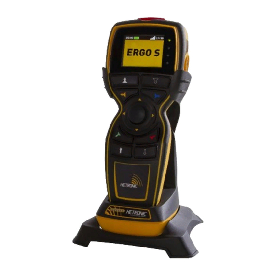
ERGO-S Transmitter 3.1 General Description The ERGO-S is an ergonomically designed, programmable wireless industrial transmitter for remote machine control. Your transmitter is encased in a rugged IP65 rated housing, is battery-powered, and comes equipped with built-in low battery detection. -
Page 8: Figure 2. Ergo-S Transmitter (Right, Front, Left)
MANUAL | ERGO-S Figure 2. Figure 2. ERGO-S Transmitter (Right, Front, Left) An optional 2.4” 240x320 TFT screen provides real An optional 2.4” 240x320 TFT screen provides real-time visual information during operation of the ERGO- -S transmitter. It is used to change... -
Page 9: Transmitter Operation Modes
Your ERGO-S transmitter’s parameters (Frequency, Baud rate, display brightness, access code, time, date and much more) can be updated without connecting to Hetronic PC-Link. When the transmitter is in this mode the user can also check proper functioning of the buttons. -
Page 10: Operating Your Transmitter
2. Insert a fully charged battery into the battery compartment of the transmitter. 3. Insert the USB key supplied with the transmitter in the ERGO-S port (#16) and press Power (#12) button to power ON the transmitter unit. 4. Enter Access code (if enabled in Hetronic PC-Link configuration). -
Page 11: Led Behaviour And Meanings
4.8 Magnetic Belt Clip (if equipped) The practical magnetic belt clip allows the user to hang the ERGO-S transmitter to any steel surface and continue operation hands free or store the transmitter hung vertically when not in use and have easy access to it. -
Page 12: Start-Up Sequences
Stop Switch (#15) + Start Switch (#12) + Lower Right Switch (#10) Copy USB Graphics Stop Switch (#15) + Start Switch (#12) + Lower Left Switch (#11) Wireless Hetronic PC-Link Stop Switch (#15): Active only for the initial 5s after Power Up Shutdown Stop Switch (#15) + Start Switch (#12) Table 3. -
Page 13: Configuring Your Ergo-S
Link to Save Settings File on USB key Note: This method is an alternative to saving the configuration f Note: This method is an alternative to saving the configuration file from Hetronic PC-Link directly on the transmitter Link directly on the transmitter (as in 5.1.1). - Page 14 PROGRAMMING AND SERVICE MANUAL | ERGO-S 5.2.2 Adjusting Settings in Service Mode The four topmost buttons on the front panel are used to navigate through Service Mode and also to change setting parameters within the menus. The menu selection changes with every screen and the description of what each of the four buttons will do is explained next to the button number.
-
Page 15: Setting Up Your Ergo-S For Operation
The coder address with which the ERGO-S transmitter has been programmed from the factory can be found listed on the datasheet. This can be updated via Hetronic PC-Link in the ‘RF’ tab and any number between 1 and 999999 can be used. The user is also able to read the coder address from the transmitter when the option ‘About’... -
Page 16: Communication
6.2.1 Radio Settings The ERGO-S coder is designed with the possibility to connect two on board RF modules either operating in the sub 1GHz range as well as MFS2G4 and CS2400. When the RF module is plugged directly on to the coder (onboard), the user may select the frequency channel or group to use for communication. -
Page 17: Figure 8. Radio Settings Menu
4800 or 9600bits/second for the Hetronic standard 4xx-8xx MHz radio modules. The standard baud rate of 115200 radio modules. The standard baud rate of 115200 bits/second is used for Hetronic standard 2.4GHz radio modules. radio modules. To change the TX Baud... -
Page 18: Figure 10. Half Duplex Configuration
6.2.5 MFS 2.4GHz Radio Mode The presence of internal 2G4 radio allows the ERGO-S coder to operate in MFS 2G4 mode. MFS Channels – There are 16 channels available for selection of the primary and secondary channels of operation. The ... -
Page 19: Configuration
6.3.1 DK Assignment Your ERGO-S transmitter can have 8 front and 4 side switches (for V1 and V2 type). These switches can be configured from the H-Link DK tab and each switch can be assigned with 3 different DK’s. The front switches can be 1 step or 2 step switches, depending on the coder, and the side switches can only be 1 step. -
Page 20: Figure 15. Assigning Telegram Dk Logic Gates
This is normally 2 seconds after #15 is pressed, however the shut down delay can be configured to last up to 7.5 seconds. This can be set on Hetronic PC-Link from the ‘Shut Down Delay’ Timer on the DK tab. -
Page 21: Ak-Dac
By adjusting the joystick analogue input sensitivity level from the bar in H By adjusting the joystick analogue input sensitivity level from the bar in Hetronic PC-Link, the speed by which the analogue input updates is by which the analogue input updates is configured. -
Page 22: Figure 20. Information Provided In The 'About' Screen
After connecting the transmitter to Hetronic PC-Link, the user has to click on “Connect” on the Link, the user has to click on “Connect” on the ‘Device Status’ tab and the status status bar changes to green which denotes communication. -
Page 23: Feedback Messages
6.6 Feedback Messages Customized LCD feedback is used for ERGO-S and this is handled through the LCD and LEDs next to the LCD. This mode allows the display of images in any location on the LCD and decoding of the feedback data as required by user without the need to follow any particular graphics mode. -
Page 24: Access Codes
500ms to 5 seconds and the image displayed can be configured through the Hetronic Graphics Programmer. Should the user not wi 500ms to 5 seconds and the image displayed can be configured through the Hetronic Graphics Programmer. Should the user not wish to have a timeout image being displayed then a blank white screen can be set in the GUI timeout screen settings. -
Page 25: Usb Interface
ERGO-S in place of the battery. The special battery enclosure consists of a module which has t . The special battery enclosure consists of a module which has to be configured via Hetronic PC etronic PC-Link (from ‘RF’ tab) for CAN or RS232 communication. - Page 26 6.10.1 Installation of Cable Control Cable 1. Switch off ERGO-S and remove the battery. 2. Plug in the cable in the ERGO-S, making sure the clips are securely fastened. 6.10.2 Operation of ERGO-S in Cable Control Mode With cable control cable attached, switch on transmitter following the start up sequence as outlined in Section 4. During start up, the transmitter will automatically recognize that the cable is attached and communicating and thus will switch into cable control mode.
-
Page 27: Theory Of Operation
Operation Your ERGO-S transmitter works with a receiving device to transfer machine control commands via radio frequency to your machine. The transmitter electronically generates a carrier frequency that allows it to communicate with the receiver without the use of cables or wires. The receiver then converts the carrier frequency information into discrete machine control outputs that interface with your machine’s controls. -
Page 28: Flash Programming
Tools required: Keil ULink 2 and uVision 4 1. Connect the “ULINK USB-JTAG Adapter” to the ERGO-S board’s JTAG (JTAG designator) connector. Square pad is pin 1. 2. Press the Power on button of the transmitter and keep it held until programming is completed. - Page 29 4. The application will display as ‘scanning port’ and indicate the details of the board connected. Note: - Application should displace device name as “ERGO-S” with Boot loader memory from ‘0’ to ‘4000h’ and Application memory from ‘4000h’ to ‘0x3C000h’.
-
Page 30: Troubleshooting
ERGO-S 9. T roubleshooting If your ERGO-S does not operate after normal start-up, follow the recommended troubleshooting sequence to help isolate the cause and determine corrective action. If you need more information, contact your dealer or Hetronic. PROBLEM PROBABLE CAUSE... -
Page 31: Specifications
Humidity Range 95% IEC 60068-2-78 Response Time Less than 100 msec. Fully programmable via Hetronic PC-Link USB (Type A) Interface with 4Gb Memory key for configuration settings Status LED for std/adv. low battery detection and Feedback LEDs Standard Features STOP Button EN 60204-1, ISO 13850, IEC60947 Compliant... -
Page 32: Warranty, Service, Repairs And Maintenance
Hetronic may replace the product or faulty parts. Work under guarantee/warranty must be carried out by Hetronic, or by an authorized service centre specified by Hetronic. Any modification, reconstruction or extension of the systems without a written agreement of Hetronic may lead to the loss of your warranty and guarantee claims. -
Page 33: Regulatory Information
As a designer and manufacturer of electrical and electronic products covered by RoHS and RoHS2, Hetronic confirms that to the As a designer and manufacturer of electrical and electronic products covered by RoHS and RoHS2, Hetronic confirms that to the best of its... -
Page 34: Industry Canada (Ic/Ised) Statement
Hetronic. Technical information subject to change without ut notice. Hetronic reserves the right to discontinue, make make changes to, and add improvements upon its products at at any time without public notice or obligation. Hetronic disclaims liability for any claims... -
Page 35: Definition Of Terms
PROGRAMMING AND SERVICE MANUAL | ERGO-S Appendix A Definition of terms The following terms are used throughout the ERGO-S Programming and Service Manual. Term Definition baud rate The transmitting speed measured in bits per second. hamming distance A measurement of data transmission safety. The amount of failures in the data stream which has to occur during the transmission in order to create a wrong signal. -
Page 36: Operator Safety Basics
Hetronic products: Instructions, manuals, and safety warnings of the manufacturers of the equipment where Hetronic products are used, Plant safety rules and procedures of the employers and the owners of the facilities where the Hetronic products are being used, ... -
Page 37: Spare Parts List
Always contact your nearest Hetronic dealer or service center for service and maintenance work on the product. Below is a list of spare parts, together with their part number, which by time may need to be replaced due to wear and tear:... - Page 38 PROGRAMMING AND SERVICE MANUAL | ERGO-S 5. Make sure that all ribbons, joystick wires and RF antenna are well aligned and secured in place and none of them are withi 5. Make sure that all ribbons, joystick wires and RF antenna are well aligned and secured in place and none of them are withi 5.
-
Page 39: Removal Of Usb Key
PROGRAMMING AND SERVICE MANUAL | ERGO-S C.3 Removal of USB Key The USB Key can be removed from the transmitter to be replaced by another one or to update graphics or configuration file. The below steps are to be followed cautiously so as to replace a USB Key without causing any damage to the housing, rubber or USB Key itself: 1.
Need help?
Do you have a question about the ERGO-S and is the answer not in the manual?
Questions and answers