Table of Contents
Advertisement
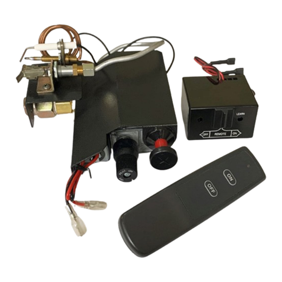
VLRK-OO REMOTE ON/OFF SAFETY PILOT VALVE
KIT WITH PROPANE CONVERSION
WARNING: If the information in this manual is not
followed exactly, a fire or explosion may result causing
property damage, personal injury or loss of life.
— Do not store or use gasoline or other flammable va-
pors and liquids in the vicinity of this or any other
appliance.
— WHAT TO DO IF YOU SMELL GAS
• Do not try to light any appliance.
• Do not touch any electrical switch; do not use any
phone in your building.
• Immediately call your gas supplier from a neighbor's
phone. Follow the gas supplier's instructions.
• If you cannot reach your gas supplier, call the fire
department.
— Installation and service must be performed by a quali-
fied installer, service agency or the gas supplier.
INSTALLER: Leave this manual with the appliance.
CONSUMER: Retain this manual for future reference.
Questions, problems, missing parts? Before returning to your retailer, call
our customer service department at 1-866-762-4050, 8:00 am - 4:30 pm CST,
Monday through Friday or email contact@bluegrassliving.com
Advertisement
Table of Contents

Related Manuals for Bluegrass Living VLRK-OO


Summary of Contents for Bluegrass Living VLRK-OO
- Page 1 VLRK-OO REMOTE ON/OFF SAFETY PILOT VALVE KIT WITH PROPANE CONVERSION WARNING: If the information in this manual is not followed exactly, a fire or explosion may result causing property damage, personal injury or loss of life. — Do not store or use gasoline or other flammable va- pors and liquids in the vicinity of this or any other appliance.
-
Page 2: Table Of Contents
TABLE OF CONTENTS Specifications ..........3 Care and Maintenance ......14 Safety ............3 Accessories ..........14 Product Features ........5 Troubleshooting ........15 Local Codes..........5 Replacement Parts ........16 Air For Combustion and Ventilation ... 6 Parts ............16 Installation .......... -
Page 3: Specifications
SPECIFICATIONS Please make sure that all of the specifications Note: This vented appliance must be installed shown are applicable before installation is only in a solid-fuel burning fireplace with a working flue and constructed of noncombus- attempted. tible material. The fireplace must include a working flue and The charts indicate technical information venting system with the minimum openings regarding the installation of your gas log set. - Page 4 SAFETY 5. You must operate this log set with a fire- WARNING: Any change to place screen in place. Make sure fireplace this log set or its controls can screen is closed before running log set. If be dangerous. the fireplace has glass doors, they must remain OPEN while this log set is in op- eration.
-
Page 5: Product Features
VLRK-OO REMOTE ON/OFF SAFETY PILOT VALVE KIT WITH PROPANE CONVERSION This VLRK-OO Vented Remote Valve Kit contains a control valve certified by C.S.A., which provides a safe and convenient way to ignite and operate your Vented Gas Log Set.. This system requires no matches, batteries, or other sources to light. -
Page 6: Air For Combustion And Ventilation
AIR FOR COMBUSTION AND VENTILATION Home owners weather strip and caulk around WARNING: If the area in which windows and doors to keep the cold air out the heater may be operated does and the warm air in. During heating months, not meet the required volume for home owners want their homes as airtight as possible. - Page 7 These items provided with Burner System 1. Determine which side the gas line will be and are not included in VLRK-OO kit. coming into the fireplce. Gas line is on the right side. This unit Remove logs, hearth kit, pan materials, is manufactured with the gas inlet on the andhardware from carton.
- Page 8 INSTALLATION 9. Place the cut-out of the Heat Shield (see figure ) over the elbow and place it down against the body of the Control Valve. Line up the mounting holes with the threaded holes in the control valve body. Install Php. Head Machine Screws.
- Page 9 REMOTE RECEIVER/TRANSMITTER IMPORTANT! THE REMOTE RECIEVER MUST BE POSITIONED WHERE AMBIANT TEMPERATURES DO NOT EXCEED 130 DEG. F. The LED signal light should illuminate when either the ON or OFF button is pressed. If the signal light does not illuminate, check Learning button the position of the battery, and verify the...
- Page 10 INSTALLING LOGS Connect the Gas Supply to the Gas Inlet of WARNING: Failure to posi- the control at the location of the Gas Inlet (See tion the parts in accordance with Figure 5 page 8)using a installer supplied fit- these diagrams or failure to use ting best for the installation.
- Page 11 CHECKING GAS CONNECTIONS Test Pressures Equal To or Less Than 1/2 PSIG (3.5 kPa) 1. Close equipment shutoff valve (see Fig- ure 13). 2. Pressure supply piping system by either Gas Meter using compressed air or opening gas supply tank valve. Check all joints from gas meter to equip- ment shutoff valve (See Figure 14).
-
Page 12: Operation
LIGHTING INSTRUCTIONS • If control knob does not pop up when WARNING: If you do not fol- released, contact a qualified service techni- low these instructions exactly, cian or gas supplier for repairs. a fire or explosion may result 6. With control knob pressed in, push down causing property damage, per- and hold ignitor button for a few seconds. - Page 13 TO TURN OFF GAS TO APPLIANCE Shutting Off Appliance Shutting Off Burner Only (pilot stays lit) 1. Push in control knob slightly and turn Push in and turn knob clockwise clockwise to the OFF position. Do the PILOT position. not force. 2.
-
Page 14: Inspecting Burners
INSPECTING BURNERS PILOT FLAME PATTERN Figure 17 shows a correct and incorrect pi- If pilot flame pattern is incorrect, as shown lot flame patterns. The incorrect pilot flame • turn fireplace off (see To Turn Off Gas to is not touching the thermocouple. This will Appliance, page 13) cause the thermocouple to cool, which •... -
Page 15: Troubleshooting
TROUBLESHOOTING WARNING: If you smell gas: • Shut off gas supply. • Do not try to light any appliance. • Do not touch any electrical switch; do not use any phone in your building. • Immediately call your gas supplier from a neighbor’s phone. Fol- low the gas supplier’s instructions. -
Page 16: Replacement Parts
REPLACEMENT PARTS Note: Use only original replacement parts. This will protect your warranty coverage for parts replaced under warranty. PARTS UNDER WARRANTY Contact authorized dealers of this product. • Model and serial number of your heater If they can’t supply original replacement •... - Page 17 PARTS LIST 7 (205) 8 (222) 9 (245) www.bluegrassliving.com 164003-01A...
-
Page 18: Warranty
Bluegrass Living makes no other warranties regarding this product. Bluegrass Living’s liability is limited to the purchase price of the product and Bluegrass Living shall not be liable for any other damages whatsoever under any circumstances including direct, indirect, incidental, or consequential damages.
Need help?
Do you have a question about the VLRK-OO and is the answer not in the manual?
Questions and answers