Table of Contents
Advertisement
Quick Links
PAIRGAIN TECHNOLOGIES
Technical Practice
Engineering - PLANT Series
P
G
AIR
CONTENTS
CAUTION
This product incorporates static sensitive
components. Proper electrostatic discharge
procedures must be followed.
T
AIN
ECHNOLOGIES
MODEL FRL-776 List 1
PairGain # 150-1376-01
PAGE
2
2
3
4
4
4
4
5
8
8
8
™
PG-F
RT L
LEX
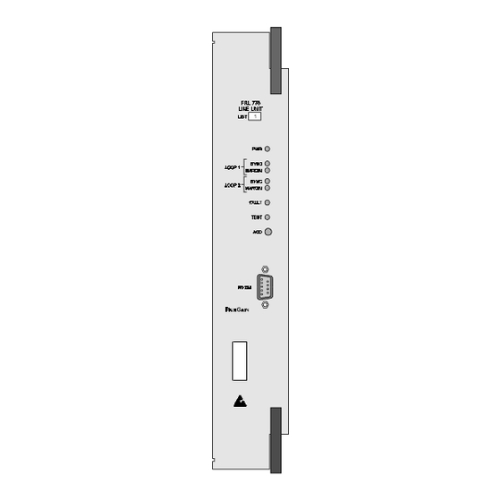
Figure 1. FRL-776 RT Line Unit, List 1, Front Panel. The
PairGain FRL-776 is the remote end of a PG-Flex subscriber
carrier system.
Section 363-776-100
Revision 01
March 4, 1996
U
INE
NIT
Page 1
Advertisement
Table of Contents

Subscribe to Our Youtube Channel
Related Manuals for PairGain PG-FLEX RT FRL-776


Summary of Contents for PairGain PG-FLEX RT FRL-776
-
Page 1: Table Of Contents
11. TROUBLESHOOTING CAUTION This product incorporates static sensitive components. Proper electrostatic discharge procedures must be followed. Figure 1. FRL-776 RT Line Unit, List 1, Front Panel. The PairGain FRL-776 is the remote end of a PG-Flex subscriber carrier system. Page 1... -
Page 2: Product Overview
Remote Terminal or pair selection. communicates with, and is line-powered The FRL-776 RT Line Unit resides in a PairGain 1.02 from, the COT over two pairs of 19- to 26- RT Enclosure; one FRL-776 RT Line Unit is gauge (0.9 mm to 0.4 mm) twisted-pair required for the system. -
Page 3: Specifications
Section 363-776-100 Revision 01 Figure 2. Typical PG-Flex Configuration. TABLE 1. PG-FLEX DISTANCES Loop Length Wire Gauge 16/32 Channel System Resistance 26 AWG (0.4 mm) 08.1 kft (2.5 km) 24 AWG (0.5 mm) 10.7 kft (3.3 km) 22 AWG (0.6 mm) 13.7 kft (4.2 km) 19 AWG... -
Page 4: Certification
This module should not be field repaired. If it 5.02 fails, replace it with another unit and return the faulty unit to PairGain for repair. Any modifications of the unit by anyone other than an authorized PairGain representative will void the warranty. -
Page 5: Front Panel
Section 363-776-100 Revision 01 Figure 3. FRL-776 Block Diagram. Off —HDSL line 2 does not detect an active 7. FRONT PANEL remote unit. 7.01 The front panel of the FRL-776 contains the • LOOP 2 MARGIN LED Indicator following switch, indicators, and connector (see Yellow—... -
Page 6: Terminal Management
Section 363-776-100 Revision 01 8. TERMINAL MANAGEMENT IDLE: The channel is not off-hook or ringing. 8.01 The terminal management function at the RING: The channel is ringing. remote terminal enables a technician to monitor the entire PG-Flex system through an ASCII terminal (or OH: The channel is off-hook. - Page 7 Section 363-776-100 Revision 01 Figure 4. FRL-776 DB-9 Pin Outs. A standard RS-232 (DB-9) connector on the front panel provides access to the menu interface feature via an ASCII terminal. Figure 5. Terminal Menu and Display Structure. Page 7...
-
Page 8: Installation And Test
PG-Flex terms. ensure complete and accurate shipment. If the shipment is short or irregular, contact PairGain as described in Section 5. If you TABLE 2. FRL-776 RT LINE UNIT TURN-UP AND TESTING CAUTION Observe normal electrostatic discharge precautions when handling electronic equipment. Do not hold electronic plug-ins by their edges. - Page 9 Section 363-776-100 Revision 01 TABLE 3. FRL-776 RT LINE UNIT TROUBLESHOOTING Indicatio Problem Action POWER 1. One or both HDSL lines a. Make the following measurement on the RT Enclosure backplane: LED off are no longer connected • 130 Vdc to 250 Vdc between A_HDSL_T and B_HDSL_T between the COT and b.
- Page 10 The number of seconds the HDSL loop was out of synchronization. This value is a running total of the last 24 hours. (Unavailable Seconds) Copyright © 1996, PairGain Technologies, Inc. PairGain is a registered trademark, CopperOptics and PG-Flex are trademarks of PairGain Technologies, Inc. Page 10...
Need help?
Do you have a question about the PG-FLEX RT FRL-776 and is the answer not in the manual?
Questions and answers