Table of Contents
Advertisement
Quick Links
Advertisement
Table of Contents

Related Manuals for PairGain PG-Flex FLC-704


Summary of Contents for PairGain PG-Flex FLC-704
- Page 1 PG-F HANNEL ENTRAL FFICE ERMINAL POTS U TART ROUND TART Model List Number Part Number FLC-704 150-1304-04 ECHNOLOGIES NGINEERING ERVICES ECHNICAL RACTICE ™363-704-104-01,¨ 363-704-104-01 ECTION...
- Page 2 PairGain is a registered trademark, and PG-Flex is a trademark of PairGain Technologies, Inc. Information contained in this document is company private to PairGain Technologies, Inc., and shall not be modified, used, copied, reproduced or disclosed in whole or in part without the written consent of PairGain.
- Page 3 363-704-104-01, Revision 01 Using This Technical Practice SING ECHNICAL RACTICE Two types of messages, identified by icons, appear in the text. Notes contain information about special circumstances. Cautions indicate the possibility of equipment damage or the possibility of personal injury. FLC-704 List 4 June 22, 1998...
-
Page 4: Table Of Contents
Table of Contents 363-704-104-01, Revision 01 ABLE OF ONTENTS Product Overview _____________________________________________________________________ 1 Description and Features ........................1 Front Panel............................2 Specifications ............................ 3 Operational Capabilities ........................4 Circuit Operation ..........................4 Loop Start Operation......................4 Ground Start Operation ....................... 6 CLASS Features........................ -
Page 5: Product Overview
RODUCT VERVIEW ® This section provides a product description, and defines the features and specifications for the PairGain PG-Flex™ FLC-704 List 4 Central Office Terminal (COT) Channel Unit. Description and Features The FLC-704 List 4 channel unit provides eight loop start or ground start channel interfaces for Plain Old Telephone Service (POTS) between a PG-Flex COT and the Central Office (CO) switch using A-Law pulse code modulation (PCM) encoding. -
Page 6: Front Panel
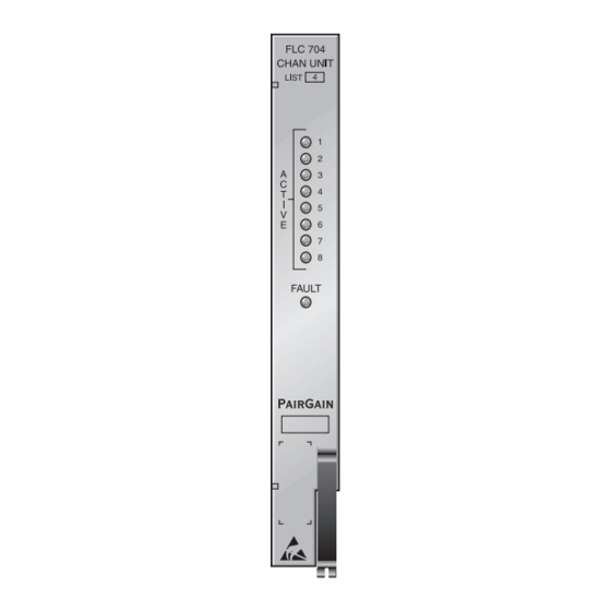
FLC-704 channel unit front panel LEDs. FLC 704 CHAN UNIT LIST Status LEDs FAULT Fault LED PairGain Warranty control number label Bar code label Figure 1. FLC-704 List 4 Front Panel Table 1. FLC-704 List 4 Front Panel LEDs and Labels LED and Label Function Solid green: Channel is off-hook. -
Page 7: Specifications
363-704-104-01, Revision 01 Product Overview Specifications Electrical Characteristics 600 Ω Analog Impedance 100 Ω, (CO switch to COT) maximum Loop Resistance End-to-End Loss –2.5 dB ±1.0 dB at 100 Hz 500 Ω Ring-Ground Resistance Channel Signature Loop Start Lines Ground Start Lines 23.75k Ω, 1% Tip-Ring (open) -
Page 8: Operational Capabilities
Product Overview 363-704-104-01, Revision 01 Operational Capabilities The FLC-704 List 4 channel unit provides eight loop start or ground start POTS interfaces to the CO switch. The unit performs the interface function between the analog POTS circuit and the internal digital pulse coded modulation (PCM) bus. - Page 9 363-704-104-01, Revision 01 Product Overview Table 3. Circuit Interactions When a Subscriber Initiates an Outgoing Call (Loop Start) Operation CO Switch FLC-704 List 4 COCU FRL-754 List 4 RTCU Subscriber ⇒ ⇒ CO Idle No ringing No ringing ⇐ ⇐ Subscriber goes Off-hook Off-hook...
-
Page 10: Ground Start Operation
Product Overview 363-704-104-01, Revision 01 Ground Start Operation The following section summarizes the ground start sequences for on-hook (idle), subscriber inititated outgoing calls, subscriber received incoming calls, and busy conditions. Idle Condition. Ground start idle condition is a Tip-lead open and Ring-lead negative from the CO and Tip lead open and Ring-lead negative at the RT (see Table 6 for circuit interactions). -
Page 11: Class Features
363-704-104-01, Revision 01 Product Overview Subscriber Receives Incoming Call. The following occurs for an incoming call (see Table 8 interactions): • FLC-704 detects a ringing signal from the CO, along with Tip-ground • FLC-704 signals the FRC-754 to connect Tip-ground and ringing to the PBX •... -
Page 12: Installation And Test
Upon receipt of the equipment: Unpack each container and visually inspect it for signs of damage. If the equipment has been damaged in transit, immediately report the extent of damage to the transportation company and to PairGain. Order replacement equipment if necessary. -
Page 13: Verify Installation
363-704-104-01, Revision 01 Installation and Test Verify Installation After the PG-Flex system is powered up and HDSL communication is synchronized: Verify that the front panel ACTIVE indicators are all OFF and the FAULT indicator is OFF (no calls are in progress). -
Page 14: Troubleshooting
4 Check the level at the COT coming from the CO switch. If it is correct, replace the COT Channel Unit. If it is not correct, refer the problem to the CO regarding the switch. 5 If the level is still not correct, re-insert the original COT Channel Unit. Contact PairGain technical assistance per “Product Support”... -
Page 15: Product Support
Do not try to repair the unit. If it fails, replace it with another unit and return the faulty unit to PairGain for repair. Any modifications of the unit by anyone other than an authorized PairGain representative voids the warranty. -
Page 16: Fcc Compliance
The FCC requires the user to be notified that any changes or modifications made to this device that are not expressly approved by PairGain Technologies, Inc. may void the user's authority to operate the equipment. All wiring external to the products should follow the provisions of the current edition of the National Electrical... -
Page 17: Abbreviations
363-704-104-01, Revision 01 Abbreviations BBREVIATIONS 2B1Q 2 binary bits encoded in one quaternary symbol American Wire Gauge CLASS Custom Local Area Signaling Services Central Office Central Office Terminal Digital Signal Level Zero (64 kb/s) DTMF Dual Tone Multi Frequency HDSL High-bit-rate Digital Subscriber Line kbps KiloBits Per Second... - Page 20 Corporate Office 14402 Franklin Avenue Tustin, CA 92780 Tel: (714) 832-9922 Fax: (714) 832-9924 For Technical Assistance: (800) 638-0031...
Need help?
Do you have a question about the PG-Flex FLC-704 and is the answer not in the manual?
Questions and answers