Cisco 1700 Hardware Installation Manual
Secure firewall management center
Hide thumbs
Also See for 1700:
- Regulatory compliance and safety information manual (45 pages) ,
- Configuring (34 pages) ,
- Manual (15 pages)
Table of Contents
Advertisement
Quick Links
Advertisement
Table of Contents

Related Manuals for Cisco 1700


Summary of Contents for Cisco 1700
- Page 1 Cisco Secure Firewall Management Center 1700, 2700, and 4700 Hardware Installation Guide First Published: 2023-11-27 Americas Headquarters Cisco Systems, Inc. 170 West Tasman Drive San Jose, CA 95134-1706 http://www.cisco.com Tel: 408 526-4000 800 553-NETS (6387) Fax: 408 527-0883...
- Page 2 Cisco has more than 200 offices worldwide. Addresses and phone numbers are listed on the Cisco website at www.cisco.com/go/offices. Cisco and the Cisco logo are trademarks or registered trademarks of Cisco and/or its affiliates in the U.S. and other countries. To view a list of Cisco trademarks, go to this URL: https://www.cisco.com/c/en/us/about/legal/trademarks.html.
-
Page 3: Table Of Contents
Site Environment Site Considerations Power Supply Considerations Rack Configuration Considerations C H A P T E R 3 Rack-Mount the Chassis Unpack and Inspect the Chassis Rack-Mount the Chassis Cisco Secure Firewall Management Center 1700, 2700, and 4700 Hardware Installation Guide... - Page 4 Contents C H A P T E R 4 Installation, Maintenance, and Upgrade Power Button Shutdown Remove and Replace a Drive Remove and Replace a Power Supply Cisco Secure Firewall Management Center 1700, 2700, and 4700 Hardware Installation Guide...
-
Page 5: Overview
Power Cord Specifications, on page 16 Features The Cisco Secure Management Center 1700, 2700, and 4700 management appliances run software that provides extensive intelligence about the users, applications, devices, threats, and vulnerabilities that exist in your network. It also uses this information to analyze your network’s vulnerabilities. It then provides tailored recommendations on what security policies to put in place and what security events you should investigate. - Page 6 Overview Features Figure 1: Cisco Secure Management Center 4700 The following table lists the features of the 1700, 2700, and 4700. Table 1: 1700, 2700, and 4700 Features Feature 1700 2700 4700 Form factor 1 RU Rack mount Standard 19-inch (48.3 cm) 4-post EIA rack...
- Page 7 RAID 5, hot-swappable RAID 6, hot-swappable RAID controller The chassis has a dedicated internal riser for a PCIe-style Cisco modular RAID controller card. Internal component only; not field replaceable. Cisco Secure Firewall Management Center 1700, 2700, and 4700 Hardware Installation Guide...
-
Page 8: Package Contents
Documentation Portal. Serial Number Locations The serial number (SN) for the 1700, 2700, and 4700 is printed on the pullout asset card located on the front panel as shown in the following figure of the 1700. Cisco Secure Firewall Management Center 1700, 2700, and 4700 Hardware Installation Guide... - Page 9 The serial number is also on the label on the cover of the chassis as shown in the following figure. Caution The cover latch on the top of the chassis cover is not supported. There are no internal field-replaceable parts in the 1700, 2700, and 4700. Cisco Secure Firewall Management Center 1700, 2700, and 4700 Hardware Installation Guide...
-
Page 10: Front Panel
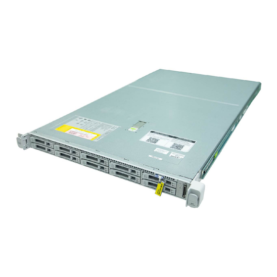
Front Panel The following figure shows the front panel features and disk-drive configuration for the 1700. See Front Panel LEDs, on page 9 for a description of the LEDs. - Page 11 The following figure shows the front panel features and disk-drive configuration for the FMC 2600. See Front Panel LEDs, on page 9 for a description of the LEDs. Cisco Secure Firewall Management Center 1700, 2700, and 4700 Hardware Installation Guide...
- Page 12 The following figure shows the front panel features and disk-drive configuration for the FMC 4600. See Front Panel LEDs, on page 9 for a description of the LEDs. Cisco Secure Firewall Management Center 1700, 2700, and 4700 Hardware Installation Guide...
-
Page 13: Front Panel Leds
Pullout asset card KVM port Not supported; use the VGA and USB keyboard ports instead. Front Panel LEDs The following figure shows the front panel LEDs and describes their states. Cisco Secure Firewall Management Center 1700, 2700, and 4700 Hardware Installation Guide... - Page 14 • Amber—The chassis is in standby mode. • Blue, flashing—The unit identification • Green—The chassis is in main power mode. function is activated. Power is supplied to all components. Cisco Secure Firewall Management Center 1700, 2700, and 4700 Hardware Installation Guide...
- Page 15 • Green—The chassis is operating at normal temperature. • Amber—One or more temperature sensors breached the critical threshold. • Amber, flashing—One or more temperature sensors breached the unrecoverable threshold. Cisco Secure Firewall Management Center 1700, 2700, and 4700 Hardware Installation Guide...
-
Page 16: Rear Panel
CIMC port (labeled M) on a Serial Over LAN (SOL) connection to remotely monitor or manage the management center system. The following figure shows the rear panel of the 1700, 2700, and 4700. Figure 9: 1700, 2700, and 4700 Rear Panel... -
Page 17: Rear Panel Leds
• Off—No link is present. • Amber—Link speed is 100 Gbps. • Green—Link is active. • Green—Link speed is 1 Gbps. • Green, flashing—Traffic is present on the active link. Cisco Secure Firewall Management Center 1700, 2700, and 4700 Hardware Installation Guide... -
Page 18: Power Supply
• Amber—Critical error detected; 12-V main power off ( for example, overcurrent, overvoltage, or overtemperature failure). Power Supply The following table lists the specifications for each 1050-W AC power supply used in the 1700, 2700, and 4700. Table 2: Power Supply Specifications Description... -
Page 19: Hardware Specifications
Form factor RSP2 Input connector IEC320 C13/C15 Hardware Specifications The following table lists the hardware specifications for the 1700, 2700, and 4700. Table 3: 1700, 2700, and 4700 Hardware Specifications Specification 1700 2700 4700 Dimensions (H x W x D) 16.9 x 1.7 x 30 inches (42.9 x 4.3 x 76.2 cm) -
Page 20: Product Id Numbers
Each power supply has a separate power cord. Standard power cords or jumper power cords are available for connection to the 1700, 2700, and 4700. The jumper power cords for use in racks are available as an optional alternative to the standard power cords. - Page 21 Overview Power Cord Specifications Note Only the approved power cords and jumper cords provided with the 1700, 2700, and 4700 are supported. The following power cords and jumper cords are supported. Figure 11: Argentina (CAB-250V-10A-AR) Plug: IRAM 2073 Cord set rating: 10 A, 250 V Connector: IEC 60320/C13 —...
- Page 22 Connector: HS10S, C-13 to C-14 (recessed — receptacle) Figure 16: Cabinet Jumper (CAB-C13-CBN) Plug: SS10A Cord set rating: 10 A, 250 V Connector: HS10S, C-13 to C-14 — Cisco Secure Firewall Management Center 1700, 2700, and 4700 Hardware Installation Guide...
- Page 23 Cord set rating: 10 A/16 A, 250 V Connector: IEC 60320/C15 (VSCC 15) — Figure 19: India (CAB-250V-10A-ID) Plug: IS 6538-1971 Cord set rating: 16 A, 250 V Connector: IEC 60320-C13 — Cisco Secure Firewall Management Center 1700, 2700, and 4700 Hardware Installation Guide...
- Page 24 Cord set rating: 10 A, 250 V Connector: IEC 60320/C15 — (EN 60320/C15M) Figure 22: Japan (CAB-JPN-3PIN) Plug: JIS 8303 Cord set rating: 12 A, 125 V Connector: IEC 60320/C13 — Cisco Secure Firewall Management Center 1700, 2700, and 4700 Hardware Installation Guide...
- Page 25 Cord set rating: 10 A, 250 V Connector: IEC 60320/C15 — Figure 25: North America (CAB-9K12A-NA) Plug: NEMA5-15P Cord set rating: 13 A, 125 V Connector: IEC 60320/C15 — Cisco Secure Firewall Management Center 1700, 2700, and 4700 Hardware Installation Guide...
- Page 26 Cord set rating: 13 A, 250 V Connector: IEC 60320/C13 — Figure 28: Switzerland (CAB-9K10A-SW) Plug: SEV 1011 (MP232-R) Cord set rating: 10 A, 250 V Connector: IEC 60320/C15 — Cisco Secure Firewall Management Center 1700, 2700, and 4700 Hardware Installation Guide...
- Page 27 Cord set rating: 10 A, 125 V Connector: IEC 60320/C13 — Figure 30: United Kingdom (CAB-9K10A-UK) Plug: BS1363A/SS145 Cord set rating: 10 A, 250 V Connector: IEC 60320/C15 — Cisco Secure Firewall Management Center 1700, 2700, and 4700 Hardware Installation Guide...
- Page 28 Overview Power Cord Specifications Cisco Secure Firewall Management Center 1700, 2700, and 4700 Hardware Installation Guide...
-
Page 29: Installation Preparation
Use the statement number at the beginning of each warning statement to locate its translation in the translated safety warnings for this device. SAVE THESE INSTRUCTIONS Cisco Secure Firewall Management Center 1700, 2700, and 4700 Hardware Installation Guide... - Page 30 Do not operate the system unless all cards, faceplates, front covers, and rear covers are in place. Warning Statement 1073 No User-Serviceable Parts There are no serviceable parts inside. To avoid risk of electric shock, do not open. Cisco Secure Firewall Management Center 1700, 2700, and 4700 Hardware Installation Guide...
-
Page 31: Safety Recommendations
• Do not wear loose clothing or jewelry, such as earrings, bracelets, or chains that could get caught in the chassis. • Wear safety glasses if you are working under any conditions that might be hazardous to your eyes. Cisco Secure Firewall Management Center 1700, 2700, and 4700 Hardware Installation Guide... -
Page 32: Maintain Safety With Electricity
For safety, periodically check the resistance value of the antistatic strap, which should be between one and 10 megohms. Site Environment Hardware Specifications, on page 15 for information about physical specifications. Cisco Secure Firewall Management Center 1700, 2700, and 4700 Hardware Installation Guide... -
Page 33: Site Considerations
• Install an uninterruptible power source for your site, if possible. Rack Configuration Considerations Rack-Mount the Chassis, on page 31 for the procedure for rack-mounting the chassis. Consider the following when planning a rack configuration: Cisco Secure Firewall Management Center 1700, 2700, and 4700 Hardware Installation Guide... - Page 34 • Baffles can help to isolate exhaust air from intake air, which also helps to draw cooling air through the chassis. The best placement of the baffles depends on the airflow patterns in the rack. Experiment with different arrangements to position the baffles effectively. Cisco Secure Firewall Management Center 1700, 2700, and 4700 Hardware Installation Guide...
-
Page 35: Rack-Mount The Chassis
• Effect of damage on the installation Rack-Mount the Chassis You can install the chassis in a rack using the Cisco rack kit. The rack must be of the following type: Cisco Secure Firewall Management Center 1700, 2700, and 4700 Hardware Installation Guide... - Page 36 • The slide rails for the chassis have an adjustment range of 24 to 36 inch (610 to 914 mm). Note The slide rails supplied by Cisco Systems for the chassis do not require tools for installation if you install them in a rack that has square 0.38-inch (9.6 mm), round 0.28-inch (7.1 mm), or #12-24 UNC threaded holes.
- Page 37 Push the mounting pegs into the rack-post holes from the outside-front. c) Press the securing plate release button, labeled PUSH. The spring-loaded securing plate closes to lock the pegs in place. Cisco Secure Firewall Management Center 1700, 2700, and 4700 Hardware Installation Guide...
- Page 38 The screw threads into the static part of the rail on the rack post and prevents the chassis from being pulled out. Repeat for the opposite slam latch. Cisco Secure Firewall Management Center 1700, 2700, and 4700 Hardware Installation Guide...
- Page 39 To avoid data loss or damage to your operating system, perform a graceful shutdown of the operating system. • Graceful shutdown—Press and release the Power button. The operating system performs a graceful shutdown and the chassis goes into standby mode. The power LED is amber. Cisco Secure Firewall Management Center 1700, 2700, and 4700 Hardware Installation Guide...
- Page 40 A skilled person or qualified personnel is someone who has training or experience in the equipment technology and understands potential hazards when working with equipment. There are no serviceable parts inside. To avoid risk of electric shock, do not open. Cisco Secure Firewall Management Center 1700, 2700, and 4700 Hardware Installation Guide...
- Page 41 Figure 34: Remove the Drive Ejector handle Release button Step 2 Remove the four drive-tray screws that secure the drive to the tray and then lift the drive out of the tray. Cisco Secure Firewall Management Center 1700, 2700, and 4700 Hardware Installation Guide...
- Page 42 Caution When you replace power supplies, do not mix power supply types in the chassis. Both power supplies must be the same wattage and Cisco PID. Cisco Secure Firewall Management Center 1700, 2700, and 4700 Hardware Installation Guide...
- Page 43 (EMI) that might disrupt other equipment, and they direct the flow of cooling air through the chassis. Do not operate the system unless all cards, faceplates, front covers, and rear covers are in place. Cisco Secure Firewall Management Center 1700, 2700, and 4700 Hardware Installation Guide...
- Page 44 Step 1 Remove the power supply: a) Grasp the power supply handle while pinching the release lever toward the handle. b) Pull the power supply out of the bay. Cisco Secure Firewall Management Center 1700, 2700, and 4700 Hardware Installation Guide...
- Page 45 Connect the power cord to the new power supply. d) If you shut down the chassis, press the Power button to return it to main power mode. Cisco Secure Firewall Management Center 1700, 2700, and 4700 Hardware Installation Guide...
- Page 46 Installation, Maintenance, and Upgrade Remove and Replace a Power Supply Cisco Secure Firewall Management Center 1700, 2700, and 4700 Hardware Installation Guide...
Need help?
Do you have a question about the 1700 and is the answer not in the manual?
Questions and answers