Table of Contents
Advertisement
Quick Links
Advertisement
Table of Contents

Related Manuals for Solenso Sol-H350H


Summary of Contents for Solenso Sol-H350H
- Page 1 Single-phase Microinverter User Manual Sol-H350H Sol-H400H...
- Page 2 PV module, consequently improving the flexibility and reliability of the system About the Manual This manual contains important instructions for the Sol-H350H/Sol-H400H Microinverter and must be read in its entirety before installing or commissioning the equipment. For safety purposes, only a qualified technician who has received training or has demonstrated competence may install and maintain this microinverter under the guidance of this document.
-
Page 3: Table Of Contents
CONTENTS 1. Important Notes 1.1 Product Range 1.2 Target User 1.3 Symbols Used 2. About Safety 2.1 Important Safety Instructions 2.2 Explanation of Symbols 2.3 Radio Interference Statement 3. About Product 3.1 About Single Unit 3.2 Highlights 3.3 Terminals Introduction 3.4 Dimension (mm) 4. - Page 4 Appendix 1: Installation Map Appendix 2: WIRING DIAGRAM – 230 VAC SINGLE-PHASE: WIRING DIAGRAM – 230 VAC/400 VAC THREE-PHASE: WIRING DIAGRAM – 120 VAC/240 VAC SPLIT-PHASE: WIRING DIAGRAM – 120 VAC/208 VAC THREE-PHASE:...
-
Page 5: Important Notes
1. Important Notes 1.1 Product Range This manual describes the assembly, installation, commissioning, maintenance and failure search for the following models of Solenso Microinverter: • Sol-H350H • Sol-H400H *Note: “350” means 350 W, “400” means 400 W. 1.2 Target User For safety purposes, only a qualified technician who has received training or has demonstrated competence may install and maintain this microinverter under the guidance of this document. -
Page 6: About Safety
• All repairs should be carried out by using only qualified spare parts, which must be installed in • accordance with their intended use and by a licensed contractor or authorized Solenso service representative. • Any liability arising from commercial components are delegated to their respective manufacturers. -
Page 7: Explanation Of Symbols
2.2 Explanation of Symbols Symbol Usage Treatment To comply with European Directive 2002/96/EC on Waste Electrical and Electronic Equipment and its implementation as national law, electrical equipment that has reached the end of its life must be separately collected and returned to an approved recycling facility. -
Page 8: About Product
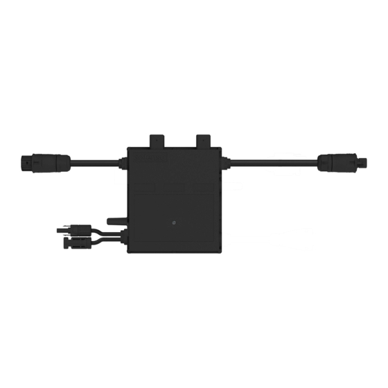
“Daisy-Chain Single Unit Microinverter” with wide DC input operating voltage range (16 V–60 V) and low start-up voltage (22 V only). The Solenso Single Unit Microinverter Sol-H350H/Sol-H400H is a reliable solution for PV systems with an uneven number of panels, and offers high CEC weighted efficiency – 96.50% (peak efficiency 96.70%) in 2015. -
Page 9: About Function
4. About Function 4.1 Work Mode Normal: In this mode, the microinverter operates normally and converts DC power into AC power to support the household loads and feeds into the public grid. Zero Export Control: In this mode, the microinverter’s generation is limited based on the current household loads, and there is no extra power fed into the public grid. -
Page 10: About Installation
5. About Installation 5.1 Accessories Object Description AC Female Connector M8 × 25 Screws DC Male Connector DC Female Connector AC Female End Cap, IP67 *Note: All accessories listed above are not included by the package, and must be purchased separately. Please contact our sales representative for price information (M8 screws need to be prepared by installer-self). -
Page 11: Required Space Distance
5.3 Required Space Distance If the microinverters are installed on a concrete roof or steel roof, their communication with the DTU may be slightly affected. Under such installation conditions, it is better for the microinverters to be installed 50 cm above the roof. Otherwise, more DTUs may be required to ensure communication quality between the 50 cm... -
Page 12: Installation Step
5.6 Installation Step Step 1. Attach Microinverter on Rail A) Mark the approximate center of each panel on the frame. B) Fix the screw on the rail. C) Hang the microinverter on the screw (as shown in the picture below), and tighten the screw. - Page 13 B) Turn on the main AC breaker of the house. Your system will start to generate power after about two minutes of waiting time. Step 7. Set Up the Monitoring System Refer to the DTU User Manual or DTU Quick Installation Guide, and Installation Guide for Solenso monitoring platform to install the DTU and set up your monitoring system.
-
Page 14: Troubleshooting
6. Troubleshooting This microinverter can only work with the new Solenso DTU (DTU-Pro, DTU-Lite and DTU-W100/DTU-G100) with the following serial number. Model Serial Number 10F7xxxxxxxx DTU-Pro 10F8xxxxxxxx 10FAxxxxxxxx DTU-G100 10D2xxxxxxxx DTU-W100 10D3xxxxxxxx DTU-Lite 10D6xxxxxxxx 6.1 Troubleshooting List Alarm Code Alarm Name Suggestion 1. - Page 15 2. If the alarms occur frequently on all the microinverters in your Island detected station, contact the local power operator to check whether there is a grid island. 3. If the alarm still exists, contact your dealer or Solenso Technical Service Center.
- Page 16 Input port overvoltage 2. If the PV module open-circuit voltage is not within the normal range, contact your dealer or Solenso Technical Service Center. 1. Please make sure that the PV module open-circuit voltage is less than or equal to the maximum input voltage.
-
Page 17: Status Led Indicator
(3) Other Status Alternating red and green flashing: Firmware is corrupted. • *Note: All faults are reported to the DTU, refer to the local DTU app or Solenso Monitoring Platform for more information. 6.3 Insulation Resistance Detection There is a resistance sensor in the microinverter to measure the resistance between the outputs of PV module and the ground. -
Page 18: On-Site Inspection (For Qualified Installer Only)
Avoid temporary repairs. All repairs should be carried out by using only genuine spare parts. If all microinverters connect to the DTU-Pro, the DTU can limit the output power imbalance of all microinverters between phases to below 3.68 kW if required. Please refer to the “Solenso Technical Note Limit Phase Balance” for more details. -
Page 19: Microinverter Replacement
Each branch should provide a circuit breaker, but a central protection unit is not required. 6.6 Microinverter Replacement a. How to remove the microinverter. De-energize the AC branch circuit breaker. • • Remove the PV panel from the racking and cover the panel. •... -
Page 20: Decommissioning
7.2 Storage and Transportation Solenso packages and protects individual components by using suitable means to facilitate the transport and subsequent handling. Transportation of the equipment, especially by road, must be carried out by using means that are suitable for protecting the components (in particular, the electronic components) from violence, shocks, humidity, vibration, etc. -
Page 21: Technical Data
DC short-circuit current. The output DC power of the PV module is NOT recommended to exceed 1.35 times the output AC power of the microinverter. Refer to the “Solenso Warranty Terms & Conditions” for more information. -
Page 22: Efficiency, Safety And Protection
Model Sol-H350H Sol-H400H Topology High-Frequency Transformers Communication 2.4 GHz Proprietary RF (Nordic) Solenso Monitoring System (Solenso Monitoring DTU is required) Warranty 12 years standard, 25 years optional VDE-AR-N 4105:2018, EN 50549-1:2019, VFR2019, Compliance AS 4777.2:2015, IEC/EN 62109-1/-2, IEC/EN 61000-3-2/-3, IEC/EN- 61000-6-1/-2/-3/-4 *Note: Voltage and frequency ranges can be extended beyond nominal if required by the utility. - Page 23 Appendix 1: Installation Map To sheet ______ To sheet Solenso Microinverter Installation Map AP040228 V1.2 Customer Information: DTU Serial Number Please Make N for North Please Make N for North Panel type: Customer Information: DTU Serial Number: Panel type: Azimuth:...
- Page 24 AC BRANCH CABLE AC BRANCH CABLE BROWN-L BROWN - L BLUE-N BLUE - N UP TO 12 HM-400S PER UP TO 12 HM-400s PER YELLOW&GREEN-G YELLOW&GREEN - G AC BRANCH CIRCUIT AC BRANCH CIRCUIT PHASE-L1 PHASE-L1 GROUND GROUND BRANCH END CAP BRANCH END CAP NEUTRAL NEUTRAL...
- Page 25 AC BRANCH CABLE AC BRANCH CABLE BROWN - L BROWN - L UP TO 12 HM-400s PER AC UP TO 12 HM-400s PER BLUE - N BLUE - N AC BRANCH CIRCUIT BRANCH CIRCUIT YELLOW&GREEN - G YELLOW & GREEN - G PHASE-L1 PHASE-L1 AC DISTRIBUTION PANEL...
- Page 26 AC BRANCH CABLE AC BRANCH CABLE BROWN - L BROWN - L BLUE - N BLUE - N UP TO 12 HM-400s PER UP TO 12 HM-400s PER YELLOW & GREEN - G YELLOW&GREEN - G AC BRANCH CIRCUIT AC BRANCH CIRCUIT PHASE-L1&L2 PHASE-L1 &...
- Page 27 AC BRANCH CABLE AC BRANCH CABLE BROWN - L BROWN - L UP TO 12 HM-400s PER UP TO 12 HM-400s PER BLUE - N BLUE - N AC BRANCH CIRCUIT AC BRANCH CIRCUIT YELLOW&GREEN - G YELLOW & GREEN - G PHASE-L1&L2 PHASE-L1 &...
- Page 28 Product Name: Energy storage integrated inverter Company Name: Solenso electronic materials Co., Ltd ADD: 4F.,No.56,Zili 5th St.,Zhongli Dist.,Taoyuan City 320,Taiwan(R.O.C.) Email: info@Solenso-global.com Web: www.Solenso-global.com...
Need help?
Do you have a question about the Sol-H350H and is the answer not in the manual?
Questions and answers