Table of Contents
Advertisement
Quick Links
Advertisement
Table of Contents

Related Manuals for Emerson Dixell Full Touch XR20T


Summary of Contents for Emerson Dixell Full Touch XR20T
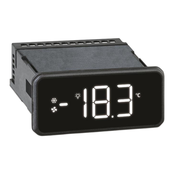
- Page 1 Full Touch XR20T - XR30T - XR60T – XR70T (V.1.5)
-
Page 3: Table Of Contents
INDEX IMPORTANT USER INFORMATION ..................................5 PRODUCT DISPOSAL (WEEE) ....................................6 GENERALITIES ........................................7 USER INTERFACE ........................................7 SCREENS ........................................7 ICONS ........................................... 8 GESTURES ........................................9 HOME BROWSING ...................................... 10 STATUS VISUALIZATION ....................................10 STAND-BY MODE ......................................10 VIRTUAL KEYBOARD ....................................11 LOCK AND ULOCK DEVICE ................................... - Page 4 13.1 DOOR SWITCH ( ) ..................................... 31 13.2 START DEFROST ( EF) ................................... 31 13.3 AUXILIARY OUTPUT ( F=AUS) ..................................31 13.4 ENERGY SAVING ( F=ES) .................................... 31 13.5 EXTERNAL WARNING ALARM ( F=EAL) ..............................31 13.6 EXTERNAL LOCK ALARM ( AL) ................................
-
Page 5: Important User Information
1. IMPORTANT USER INFORMATION • symbol is intended to alert the user of a non-insultated voltage source within the product area that is sufficiently high to constitute a risk of electric shock to persons. • symbol is intended to alert the user of important operating and maintenance (servicing) instructions. -
Page 6: Product Disposal (Weee)
• It is good practice to bear in mind the following indications for all Dixell products: Prevent the electronic circuits from getting wet as contact made with water, humidity or any other type of liquid can damage them. Comply with the temperature and humidity limits specified in the manual in order to store the product correctly. -
Page 7: Generalities
3. GENERALITIES The XR-T is a microprocessor-based controller suitable for applications on medium or low temperature ventilated refrigeration units. It has 4 relay outputs to control compressor, fans, light and defrost or auxiliary outputs. The device is also provided with up to 4 NTC, PTC or PT1000 probe inputs. There are up to 2 configurable digital inputs. -
Page 8: Icons
Parameter Menu - GrP: Parameters are grouped as logic function (ex. regulation, defrost, etc.) X9: it is possible to create the label of the parameter to be visualized or modified. Password menu: insert the password to see and modify the protected (level Pr2) parameters Info: To scroll all I/O variables and status (probes, digital inputs, digital outputs, etc.) Stand-By: in this condition all outputs are deactivated. -
Page 9: Gestures
When in the Loads Info screen: evaporator fan output OFF FLASH Activation delay is running When in the Loads Info screen: evaporator fan output ON Function not available DEFROST FLASH When in the Virtual Keyboard screen: defrost ON When in the Virtual Keyboard screen: defrost OFF Function not available FLASH When in the Virtual Keyboard screen: AUX output ON... -
Page 10: Home Browsing
Drag a finger across the screen, from top to bottom or from Modify: use vertical swipe (from top to bottom or V-SWIPE bottom to top bottom to top) to change a parameter value. (overlapping only one of the digits) 4.4 HOME BROWSING Use H-SWIPE to move through the screens. -
Page 11: Virtual Keyboard
4.7 VIRTUAL KEYBOARD The Virtual Keyboard present some direct access function which can be enabled by touching the relative icon. The activation of any function will trigger an animation effect (a “snake” moving effect on the display) and, at the end, a segment above the function icon (or below, depending on the position of the icon) will be lit. 4.8 LOCK AND ULOCK DEVICE It is possible to lock the device: Swiping-up (V-SWIPE) from HOME and then by touching the display anywhere (1 or 3 sec depending... -
Page 12: Hotkey - Download
2. Insert the HotKey (on the 5-pin ports on the back of the device) 3. Touch the the display anywhere (1 or 3 sec depending on par. bPt) 4. The copying procedure will start and will trigger an animation effect (a “snake” moving effect on the display). -
Page 13: Parameter Menu
4.13 PARAMETER MENU From the PRG screen is possible to unlock the programming menu by touching any area of the display (1 or 3 sec depending on par. bPt). 4.14 PARAMETER MENU - ALL From PrG screen it is possible to enter the Parameter Menu - ALL touching the display anywhere (1 or 3 sec depending on par. -
Page 14: Password Menu
Here are the available groups: NOTE: depending on the configuration, some parameters or entire groups of them could not be available. Group Label Description Main regulation parameters Probe configuration parameters Visualization parameters Defrost configuration parameters Evaporator and condenser fan configuration parameters Auxiliary regulator parameters Alarm configuration parameters Digital and analogue output configuration parameters... -
Page 15: Parameter Table
Move to the second char position (segment in the middle) and swipe-up or down until char “d” • appears Move on the third char position (segment on the right) and swipe-up or down until char “F” appears • • Enter the par. value by touching the PRG icon for 3 sec. NOTE: pay attention to the upper or lower case when browsing through the available characters. -
Page 16: Probe Configuration Parameters - Prb
This function is enabled after the Output activation delay at start-up 0 to 255 min instrument power-on and delays the activation of the outputs. Delay between first compressor (CP1) Anti-short cycle delay 0 to 50 min stop and the next restart. Anti-short cycle delay (2nd Delay between second compressor 0 to 255 min... -
Page 17: Visualization Parameters - Dis
Probe P3 presence n(0); Y(1) n = not present; Y = present [-12.0°C to 12.0°C] Allows to adjust any possible offset of the Probe P3 calibration [-21.6°F to 21.6°F] probe P3. Probe P4 presence n(0); Y(1) n = not present; Y = present [-12.0°C to 12.0°C] Allows to adjust any possible offset of the Probe P4 calibration... -
Page 18: Evaporator And Condenser Fan Configuration Parameters - Fan
Temperature display delay after delay before updating the temperature on 0 to 255 min any defrost cycle the display after the end of any defrost. during a draining phase the regulation is Draining time 0 to 255 min stopped. The relative output will stay on after Drain heater enabled after draining 0 to 255 min draining time. -
Page 19: Auxiliary Regulator Parameters - Aus
Std = standard mode, evaporator fan Std(0); FoF(1); follows par FnC; Fon = evaporator Fan Evaporator fan operating mode Fon(2) always on; FoF = evaporator fan always n = evaporator fan follows par. FnC Evaporator fan controlled during n(0); Y(1) during any defrost;... -
Page 20: Alarm Configuration Parameters - Alr
n = the auxiliary relay operates during Auxiliary regulator disabled during n(0); Y(1) defrost. Y = the auxiliary relay is switched any defrost cycle off during defrost Base time for parameters Ato and SEC = base time is in second; Min = SEC;... -
Page 21: Digital Output Configuration Parameters - Out
Delay between the detection of the 2nd temperature alarm delay at 0.0 to 24h00min second temperature alarm condition and 00:00 start-up the relative alarm signaling at power-on. n = the compressor continues to work; Y = the compressor is switched off while Compressor OFF due to 2nd low n(0);... -
Page 22: Digital Input Configuration Parameters - Inp
n=light output status unchanged after Light output OFF when in stand-by n(0); Y(1) stand-by. Y=light output switched off after stand-by. n=light output unchanged; Y=light output Light output ON after power-on n(0); Y(1) forced ON. 5.1.9 Digital input configuration parameters – inP LABEL DESCRIPTION RANGE... -
Page 23: Energy Saving Configuration Parameters Es
after reaching nPS events in the digital Number of external pressure input alarm delay (par. dxd), the switch alarms before stopping the 0 to 15 regulation will be stopped and a manual regulation restart (ON/OFF, power OFF and power ON) will be required no = no regulation lockout;... - Page 24 Total number of relay oA1 activations. Number of activations for relay This value is saved into controller output oA1 (units of) - Read Only memory. Number of activations for relay Total number of relay oA2 activations. output oA2 (thousands of) - Read This value is saved into controller Only memory.
-
Page 25: Real Time Clock Configuration Parameters - Rtc
5.1.12 Real Time Clock configuration parameters – rtC LABEL DESCRIPTION RANGE MEANING VALUE Hours - Read Only Real time clock: hour value Minutes - Read Only Real time clock: minutes value Day of the week - Read Only Real time clock: day of the week value Day of the month - Read Only Real time clock: calendar day value Month - Read Only... -
Page 26: Serial Communication Port Configuration Parameters - Com
Select Y and confirm to reset the MAX and Min values reset for memorized min and MAX temperature HACCP functions (valid if n(0); Y(1) values (HACCP function must be .eMiMa=1) enabled). 5.1.14 Serial Communication port configuration parameters – CoM LABEL DESCRIPTION RANGE MEANING... -
Page 27: Information, Read Only Parameters - Inf
The relative function is enable also in Button 3 enabled in stand-by n(0); Y(1) stand-by mode insert a value to protect all the Password for level Pr2 0 to 999 parameters set on the level Pr2 from modification 5.1.16 Information, read only parameters – inF LABEL DESCRIPTION RANGE... -
Page 28: Energy Saving
With parameter rCC it is possible to enable the compressor rotation function: the activation of the first and the second compressor will be alternated to equalize the number of working hours of both of them. In case of hot gas defrost operation, it is possible to select if one or both compressors will be used. 7. -
Page 29: Timed Or Temperature Controlled Mode
• EdF=rtC: by using an internal real-time clock (only for models equipped with RTC) • EdF=in: timed defrost, in this case a new defrost will start as soon as the idF timer elapses 9.1 TIMED OR TEMPERATURE CONTROLLED MODE Two defrost modes are available: timed or controlled by a temperature probe. A couple of parameters are required to control intervals between defrost cycles (idF) and maximum duration (MdF). -
Page 30: Digital Outputs
C-Y: in parallel with compressor output and always on during any defrost. When compressor is OFF, they will start a duty-cycle mode (see FoF, Fon, FF1 and Fo1 parameters) o-Y: always on DIGITAL OUTPUTS Depending on the model, one or more digital outputs (relays) can be configurated with one of the following functionalities. -
Page 31: On/Off Output (Oax = Onf)
12.8 ON/OFF OUTPUT (oAx = onF) When oAx=onF, the output is activated when the controller is switched on and deactivated when the controller is switched off. 12.9 ENERGY SAVING OUTPUT (oAx = HES) When oAx=HES, the output is activated when the energy saving mode is active and vice-versa. 12.10 CONDENSER FAN OUTPUT (oAx = Cnd) With oAx=Cnd the relay operates as a condenser fan output. -
Page 32: External Pressure Alarm (Ixf=Pal)
13.7 EXTERNAL PRESSURE ALARM (ixF=PAL) It is used to detect any pressure external alarm. This signal locks the regulation after detecting nPS events in the interval dxd. 13.8 EVAPORATOR FAN MODE (ixF=FAn) It is used to control the evaporator fan. 13.9 REMOTE HOLIDAY MODE (ixF=HdF) It is used to force the holiday mode. -
Page 33: Installation And Mounting
INSTALLATION AND MOUNTING Instrument XR-T shall be mounted on vertical panel, in a 29x71 mm hole, and fixed using the special bracket supplied. The temperature range allowed for correct operation is 0 to 60°C. Avoid places subject to strong vibrations, corrosive gases, excessive dirt or humidity. The same recommendations apply to probes. -
Page 34: Xr20T
17.4 XR20T Power Supply: 110VAC, 230VAC or 100-240VAC, 50-60Hz oA1: always set as main compressor output (CP1) 1592040000 XR20-30-60-70T EN v1.5 2023.10.12.docx XR20-30-60-70T 34/38... -
Page 35: Technical Specifications
TECHNICAL SPECIFICATIONS FEATURES DESCRIPTION Housing Self-extinguishing PC Dimensions Front fascia 38x80 mm; case depth 81mm Mounting device Panel, 71x29mm panel cut-out NEMA – UL 50e Indoor use only, Type 1 enclosure Degree of Protection IP-IEC/EN 60529 Front panel: IP66 Rear Housing: IP00 230Vac 10%, 50/60Hz;... - Page 36 FEATURES DESCRIPTION SPST 5A, Resistive load 5A, 12Vac, 50K cycles 5(1)A, 230Vac, 50K cycles 250Vac SPST 8A, Resistive load 10A 12Vac, 30K cycles 8(3)A, 230Vac, 50K cycles 250Vac For models: 12V with OA1 = 8A Nominal SPST 16A, Resistive load 10A 12Vac, 30K cycles 8(3)A, 230Vac, 50K cycles 250Vac SPDT 8A,...
-
Page 37: Appendix
APPENDIX 19.1 TOOLS 19.1.1 XH-REP The XH-REP remote display enables the visualization of a second temperature value. A special cable must be used to connect an XH-REP to the controller (code DD200002 00). The remote display usage will disable the serial communication. 19.1.2 X-MOD The X-MOD is a motion detection sensor that allows to detect the proximity of customers or service staff. -
Page 38: Example Of Menu Navigation And Parameter Modification
19.2 EXAMPLE OF MENU NAVIGATION AND PARAMETER MODIFICATION . . . TAP and HOLD anywhere TAP and HOLD anywhere TAP and HOLD anywhere to show the current value of par. “LS” V-SWIPE on every single digit to modify TAP and HOLD “SET” to save and exit 1592040000 XR20-30-60-70T EN v1.5 2023.10.12.docx XR20-30-60-70T 38/38...
Need help?
Do you have a question about the Dixell Full Touch XR20T and is the answer not in the manual?
Questions and answers