Table of Contents
Advertisement
Quick Links
Keithley Instruments
28775 Aurora Road
Cleveland, Ohio 44139
1-800-935-5595
tek.com/keithley
Introduction
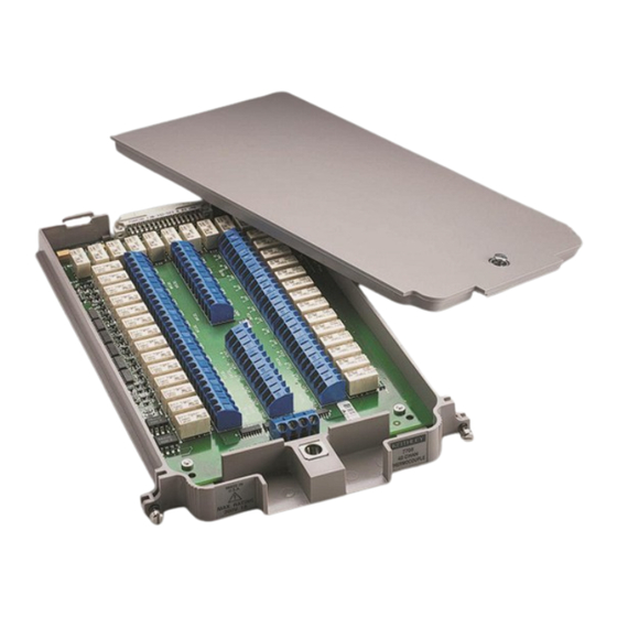
The Model 7708 40-Channel Differential Multiplexer Plug-In Module with Automatic CJC offers 40 channels
of 2-pole or 20 channels of 4-pole multiplexer switching that can be configured as two independent banks
of multiplexers. Automatic CJC is provided so that no other accessories are required to make thermocouple
measurements. The 7708 is ideal for RTD, thermistor, and thermocouple temperature applications. It is also
well suited for mixed-signal measurement applications that require multi-point monitoring, such as
environmental stress screening.
Item shipped may vary from model pictured here.
077144500 / April 2018
Figure 1: Model 7708 40-Channel Differential Multiplexer Module
*P077144500*
Model 7708 Multiplexer Module
Instructions for use with DAQ6510
1
Advertisement
Table of Contents

Related Manuals for Tektronix KEITHLEY 7708

Summary of Contents for Tektronix KEITHLEY 7708
- Page 1 Model 7708 Multiplexer Module Keithley Instruments Instructions for use with DAQ6510 28775 Aurora Road Cleveland, Ohio 44139 1-800-935-5595 tek.com/keithley Introduction The Model 7708 40-Channel Differential Multiplexer Plug-In Module with Automatic CJC offers 40 channels of 2-pole or 20 channels of 4-pole multiplexer switching that can be configured as two independent banks of multiplexers.
- Page 2 Model 7708 Multiplexer Module Instructions for use with DAQ6510 The 7708 includes the following features: ▪ DC and AC voltage measurement ▪ Two-wire or four-wire resistance measurements (automatically pairs switches for four-wire measurements—n + 20) ▪ Temperature applications (RTD, thermistor, thermocouple) ▪...
-
Page 3: Wiring Procedure
Model 7708 Multiplexer Module Instructions for use with DAQ6510 Wiring procedure Use the following procedure to make connections to the 7708 module. Make all connections using the correct wire size (up to 20 AWG). All wiring must be rated for the maximum voltage in the system. For example, if 1000 V is applied to the front terminals of the instrument, the switching module wiring must be rated for 1000 V. - Page 4 Model 7708 Multiplexer Module Instructions for use with DAQ6510 4. Route wire along the cable path and secure with cable ties as shown. The following figure shows connections to channels 1 and 2. Figure 3: Wire dressing 5. Record the connections in the Connection log (on page 8).
-
Page 5: Schematic Diagram
Model 7708 Multiplexer Module Instructions for use with DAQ6510 Schematic diagram The simplified schematic diagram of the 7708 is shown in the following figure. The channels are grouped into two banks of 20 channels (40 channels total). Backplane isolation is provided for each bank. Each bank also includes separate cold junction reference points. - Page 6 Model 7708 Multiplexer Module Instructions for use with DAQ6510 Figure 4: Model 7708 simplified schematic Channel 41 (2W/4W Configuration), Channel 42 (Sense Isolation), and Channel 43 (Input Isolation) are normally automatically configured by the DAQ6510. 077144500 / April 2018...
-
Page 7: Typical Connections
Model 7708 Multiplexer Module Instructions for use with DAQ6510 Typical connections The following examples show typical wiring connections for the following types of measurements: ▪ Thermocouple ▪ Two-wire resistance and thermistor ▪ Four-wire resistance and RTD ▪ DC or AC voltage Thermocouple connections Figure 5: Thermocouple connections Two-wire resistance and thermistor connections... - Page 8 Model 7708 Multiplexer Module Instructions for use with DAQ6510 Four-wire resistance and RTD connections Figure 7: 4-wire resistance and RTD connections DC or AC voltage connections Figure 8: Voltage connections - DC or AC 077144500 / April 2018...
-
Page 9: Connection Log
Model 7708 Multiplexer Module Instructions for use with DAQ6510 Connection log You can use the next table to record your connection information. Channel Color Description Description Color Channel INPUT SENSE CH21 CH22 CH23 CH24 CH25 CH26 CH27 CH28 CH29 CH10 CH30 CH11 CH31... -
Page 10: Installation
Model 7708 Multiplexer Module Instructions for use with DAQ6510 Installation Before operating an instrument with an accessory switching module, verify that the switching module is properly installed and the mounting screws are tightly fastened. If the mounting screws are not properly connected, an electrical shock hazard may be present. To use the switching operations, a switching module must be installed in the DAQ6510. - Page 11 Model 7708 Multiplexer Module Instructions for use with DAQ6510 Before installing or removing a switching module, make sure the DAQ6510 power is turned off and disconnected from line power. Failure to comply may result in incorrect operation and loss of data in the memory. Required equipment: ▪...
-
Page 12: Operation
Model 7708 Multiplexer Module Instructions for use with DAQ6510 Before installing or removing a switching module, make sure the DAQ6510 power is turned off and disconnected from line power. Failure to comply may result in incorrect operation and loss of data in the memory. Required equipment: ▪... -
Page 13: Environmental Conditions
Model 7708 Multiplexer Module Instructions for use with DAQ6510 This verification procedure requires that the DAQ6510 be within its calibration interval. Module verification test procedures include: ▪ DC volts ▪ AC volts ▪ Resistance ▪ Temperature ▪ Frequency ▪ Ratio and average Make sure that you perform the verification tests using the following conditions: ▪... -
Page 14: Recommended Test Equipment
Model 7708 Multiplexer Module Instructions for use with DAQ6510 Calculating resistance reading limits Resistance reading limits must be recalculated based on the actual calibration resistance values supplied by the equipment manufacturer. Calculations are performed in the same manner as shown in the previous example, except that you should use the actual calibration resistance values instead of the nominal values when performing your calculations. -
Page 15: Performance Verification Procedures
Model 7708 Multiplexer Module Instructions for use with DAQ6510 Performance verification procedures The following procedures describe how to check one channel (CH1) or one channel pair (CH1 and CH11) of the module. To check other channels or channel pairs, modify the procedures by connecting the verification equipment to the appropriate channel or channel pair. -
Page 16: Verifying Dc Voltage
Model 7708 Multiplexer Module Instructions for use with DAQ6510 Verifying DC voltage To check DC voltage accuracy, apply accurate voltages from the DC voltage calibrator to the input terminals of the module and verify that the displayed readings fall within specified limits. Do not exceed 300 VDC between plug-in module INPUT H and L terminals or between any adjacent channels. -
Page 17: Verifying Ac Voltage
Model 7708 Multiplexer Module Instructions for use with DAQ6510 Range Applied DC voltage Reading limits (1 year, 18 °C to 28 °C) 100 mV 100.0000 mV 99.9935 to 100.0065 mV 1.000000 V 0.999969 to 1.000031 V 10 V 10.00000 V 9.99970 to 10.00030 V 100 V 100.0000 V... - Page 18 Model 7708 Multiplexer Module Instructions for use with DAQ6510 2. Install the module in Slot 1 of the DAQ6510. 3. Turn on the power. 4. Allow the instrument to warm up for one hour. 5. Make sure that the front-panel TERMINALS switch is set to REAR. 6.
-
Page 19: Verifying Resistance
Model 7708 Multiplexer Module Instructions for use with DAQ6510 Verifying resistance Check resistance by connecting accurate resistance values to the module and verifying that its resistance readings are within the specified limits. Do not apply more than 300 VDC between the module INPUT or SENSE H and L terminal or between any adjacent channels. - Page 20 Model 7708 Multiplexer Module Instructions for use with DAQ6510 Nominal reading limits Nominal Ω Range Recalculated limits** resistance (1 year, 18°C to 28°C) 1 Ω* 1 Ω 0.999715 mΩ to __________ to __________ Ω 1.000285 Ω 10 Ω 10 Ω 9.99895 mΩ...
-
Page 21: Verifying Temperature
Model 7708 Multiplexer Module Instructions for use with DAQ6510 Verifying temperature Thermocouple, thermistor, and RTD temperature readings are derived from DC volts and resistance measurements, respectively. For that reason, it is not necessary to independently verify the accuracy of temperature measurements. If the DC volts and resistance functions meet or exceed specifications, temperature function accuracy is automatically verified. - Page 22 Model 7708 Multiplexer Module Instructions for use with DAQ6510 2. Install the module in Slot 1 of the DAQ6510. 3. Turn on the power. 4. Allow the instrument to warm up for one hour. 5. Make sure that the front-panel TERMINALS switch is set to REAR. 6.
- Page 23 Model 7708 Multiplexer Module Instructions for use with DAQ6510 RTD temperature To verify the RTD temperature: 1. Connect the precision decade resistance box to the CH1 and CH11 H and L terminals of the module using four-wire connections. Refer to the first figure in Verifying resistance for connections. 2.
-
Page 24: Verifying Frequency
Model 7708 Multiplexer Module Instructions for use with DAQ6510 Verifying frequency To verify the module frequency: 1. Connect the function generator to the CH1 H and L INPUT terminals of the module. Refer to the next figure for more information. 2. - Page 25 Model 7708 Multiplexer Module Instructions for use with DAQ6510 Verifying ratio and average Follow the procedure below to verify ratio and average. Do not exceed 300 VDC between plug-in module INPUT H and L terminals or between any adjacent channels. Failure to observe this precaution can cause instrument damage. Use shielded cables to minimize noise.
- Page 26 Model 7708 Multiplexer Module Instructions for use with DAQ6510 Range Applied DC voltage Reading limits (1 year, 18 °C to 28 °C) 100 mV 100.0000 mV 99.9935 to 100.0065 mV 1.000000 V 0.999969 to 1.000031 V 10 V 10.00000 V 9.99970 to 10.00030 V 100 V 100.0000 V...
-
Page 27: Factory Service
Factory service To return the switching module to Keithley Instruments for repair: ▪ Call the Repair Department at 1-800-833-9200 or send an email to RMAREQUEST@tektronix.com for a Return Material Authorization (RMA) number. ▪ Carefully pack the instrument in the original packing carton. -
Page 28: Safety Precautions
Safety precautions The following safety precautions should be observed before using this product and any associated instrumentation. Although some instruments and accessories would normally be used with nonhazardous voltages, there are situations where hazardous conditions may be present. This product is intended for use by personnel who recognize shock hazards and are familiar with the safety precautions required to avoid possible injury. - Page 29 For safety, instruments and accessories must be used in accordance with the operating instructions. If the instruments or accessories are used in a manner not specified in the operating instructions, the protection provided by the equipment may be impaired. Do not exceed the maximum signal levels of the instruments and accessories. Maximum signal levels are defined in the specifications and operating information and shown on the instrument panels, test fixture panels, and switching cards.
Need help?
Do you have a question about the KEITHLEY 7708 and is the answer not in the manual?
Questions and answers