Table of Contents
Advertisement
Quick Links
INSTALLATIEHANDLEIDING NL/BE
INSTRUCTIONS FOR INSTALLATION GB/IE
INSTALLATIONSVORSCHRIFT DE/AT/BE/LU/CH
INSTRUCTIONS D' INSTALLATION FR/BE/LU/CH
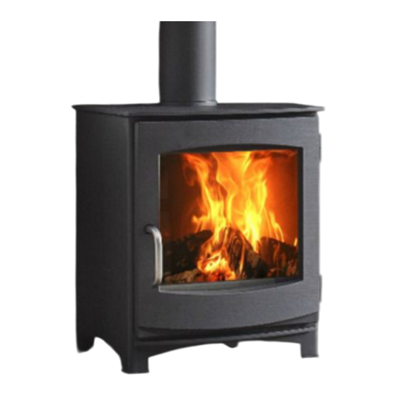
Jannik Medium Low
EA
Keld 5 Low
EA
Keld 5 High
EA
Ivar 5 Low
EA
Ivar 5 High
EA
Ivar 5 Store
EA
Aste 5 Low
Lees en bewaar dit document zorgvuldig
Please read and retain this document carefully
Dieses Dokument sorgfältig durchlesen und gut aufbewahren
Lisez et conservez soigneusement cette notice
EA
Jannik Medium Low
RS
Keld 5 Low
RS
Keld 5 High
RS
Ivar 5 Low
RS
Ivar 5 High
RS
Ivar 5 Store
RS
Aste 5 Low
RS
Advertisement
Table of Contents

Subscribe to Our Youtube Channel
Related Manuals for Dik Geurts Jannik Medium Low RS


Summary of Contents for Dik Geurts Jannik Medium Low RS
- Page 1 INSTALLATIEHANDLEIDING NL/BE INSTRUCTIONS FOR INSTALLATION GB/IE INSTALLATIONSVORSCHRIFT DE/AT/BE/LU/CH INSTRUCTIONS D’ INSTALLATION FR/BE/LU/CH Jannik Medium Low Jannik Medium Low Keld 5 Low Keld 5 Low Keld 5 High Keld 5 High Ivar 5 Low Ivar 5 Low Ivar 5 High Ivar 5 High Ivar 5 Store Ivar 5 Store Aste 5 Low...
-
Page 2: Table Of Contents
9.3.2 Flame baffle plate 9.4 Adjusting the door / Replacing door seal 9.5 Supplementary installation instructions per appliance 9.5.1 Jannik Medium Low EA / Jannik Medium Low RS 9.5.1.1 Outside air connection 9.5.1.2 Adjusting the door / Replacing door seal 9.5.1.3 Disassembly of glass pane in door... -
Page 3: Introduction
As a manufacturer of fires, DRU Verwarming develops and produces products according to the highest possible English quality, performance and safety requirements. These woodburning Dik Geurts fires are provided with a CE mark that is only awarded for fires complying with the essential requirements of the European Construction Products Regulation, including requirements made of safety, the environment and energy consumption. -
Page 4: Ec Declaration Of Conformity
IN S T A LLA TION M A N U A L 2. EC DECLARATION OF CONFORMITY The undersigned, representative of: Manufacturer: DRU Verwarming BV Postbus 1021 NL-6920 BA Duiven Ratio 8, NL-6921 RW Duiven hereby declares that the design and construction of the woodburning heating appliance supplied by DRU satisfies the essential requirements of the Construction Products Regulation and is produced and distributed according to the requirements of the Belgian Royal Decree of 12 October 2010 for the regulation of the minimum requirements of efficiency and emission levels of pollutants for solid fuel heating equipment. -
Page 5: Safety
IN S TALLAT ION M AN U AL 3. SAFETY 3.1 General • Carefully read this section about safety before you start installation or maintenance. !CAUTION • Comply with the generally applicable conditions and the precautionary measures/safety instructions in this manual. -
Page 6: Unpacking
IN S T A LLA TION M A N U A L 4. Unpacking Follow the below points below when unpacking: Ø Check the appliance with accessories for (transport) damage. Ø Never install a damaged fire! Ø If necessary contact your supplier. Keep plastic bags away from children. -
Page 7: Appliances With Fan(S)
IN S TALLAT ION M AN U AL 5.4 Appliances with fan(s) Appliances that are made with one or more fans will heat a room more quickly and increase comfort. As soon as the fan is switched on you will be able to sense a pleasant, warm air flow. The fan can be set in various positions. The air flow can leave the appliance both at the front and via the convection openings. - Page 8 IN S T A LLA TION M A N U A L Any bend in the chimney or connecting fluepipe should not exceed 45°. 90° bends should not be used. Combustible material should not be located where the heat dissipating through the walls of fireplaces or flues could ignite it.
-
Page 9: The Clean Air Act 1993 And Smoke Control Areas
IN S TALLAT ION M AN U AL Use of operating tools Always use the operating tools provided when handling parts likely to be hot when the stove is in use. Aerosol sprays Do not use an aerosol spray on or near the stove when it is alight. 5.5.2 The Clean Air Act 1993 and Smoke Control Areas 5.5.2.1 Smoke Control Areas Under the Clean Air Act local authorities may declare the whole or part of the district of the authority to be a... -
Page 10: Outside Air Connection
IN S T A LLA TION M A N U A L 5.5.2.2 Exempt appliances Exempt appliances are appliances (ovens, wood burners and stoves) which have been exempted under the Clean Air Act 1993 or Clean Air (Northern Ireland) Order 1981. Appliances which are exempt for use in Smoke Control Areas: https://smokecontrol.defra.gov.uk/appliances.php 5.6 Outside air connection (if applicable) Some fires can be provided with an outside air connection. -
Page 11: Free-Standing/Design Fires
IN S TALLAT ION M AN U AL 5.7.1 Free-standing/design fires 5.7.1.1 Conversion from fire top connection to rear connection (if applicable). The fire is supplied with a top connection for connecting the flue duct. The top connection can be converted to a rear connection. To do this proceed as follows (see Annex 2, Fig. - Page 12 IN S T A LLA TION M A N U A L Ø Carefully slide the fire into the hole. Make sure that no damage is caused. Ø If applicable connect the convection opening ( see section 5.3 'Convection') with the flexible aluminium pipe and ventilation elements (see section 5.4 'Appliances with fan(s))'.
-
Page 13: Built-In Fires
IN S TALLAT ION M AN U AL Ø Use single-walled stainless steel flue pipes or stainless steel double-walled flexible pipes that at least meet the requirements of standard EN 1856-2 T600. Ø The fire may never support the flue. Ø... -
Page 14: Completing Installation
IN S T A LLA TION M A N U A L Ø Always connect any convection openings (see section 5.3 'Convection') with heat-resistant flexible pipe and ventilation elements (see section 5.4 'Appliances wit fan(s)) to protect the plasterwork against high temperatures. If the chimney breast is made of non-combustible materials (e.g. -
Page 15: Delivery
IN S TALLAT ION M AN U AL 6. Delivery Ø You must make the user familiar with the fire. Among other things you must instruct her/him about bringing the fire into use and its burning and maintenance. Ø When bringing into use point out that •... -
Page 16: Appliance-Specific Information
IN S T A LLA TION M A N U A L 9. Appliance-specific information • The appliance-specific instructions as described in this section prevail over the instructions in the other !CAUTION sections! If in doubt follow the instructions in section 9 or contact your supplier. •... -
Page 17: Flame Baffle Plate
IN S TALLAT ION M AN U AL 9.3.2 Flame baffle plate On delivery the flame baffle plate (see Appendix 2, fig. 5) is located in the top section of the appliance. In case of maintenance to the appliance, the flame baffle plate has to be removed. To do this proceed as follows: Ø... -
Page 18: Disassembly Of Glass Pane In Door
IN S T A LLA TION M A N U A L To do this proceed as follows: Ø Loosen the nuts a little. Ø Adjust the door catches. Ø Then re-tighten the nuts properly. Ø Check whether the sealing tape makes a good connection by clamping a sheet of paper between the fire and the sealing tape when closing the door. -
Page 19: Assembly/Disassembly Of Glass Pane In Door
IN S TALLAT ION M AN U AL If you want to disassemble the outdoor air connection, you should perform the above-mentioned steps in reverse order. 9.5.2.2 Assembly/disassembly of glass pane in door • Avoid damage when removing/fitting the glass pane. !Caution •... -
Page 20: Assembly/Disassembly Of Glass Pane In Door
IN S T A LLA TION M A N U A L Ø Connect the flexible hose to the round 'pipe opening' of the above-mentioned tray. The flexible hose can only be fed from the rear. The round pipe opening for the benefit of the lower connection is not needed during installation and should be Caution! disposed of responsibly. -
Page 21: Ivar 5 Store Ea / Ivar 5 Store Rs
IN S TALLAT ION M AN U AL 9.5.4 Ivar 5 Store / Ivar 5 Store 9.5.4.1 Outside air connection Outside air connections are available for these appliances as accessories. Assembly always takes place at the bottom of the appliance. When installing an RS appliance, the outdoor air-connection is pre-mounted at delivery. - Page 22 Bijlage/Appendix/Anlage/Annexe 1: Tabellen/Tables /Tabellen/Tableaux Tabel/Table/Tabelle/Tableau 1: Meegeleverde onderdelen/Parts included/Lieferumfang/Pièces fournies Onderdeel / Part / Teil / Pièce Aantal / Quantity / Anzahl / Nombre Installatiehandleiding / Installation manual / Installationsanleitung / Manuel d’installation Gebruikershandleiding / User manual / Bedienungsanleitung / Manuel de l’utilisateur Handschoen / Glove / Handschuh / Gant Asschep / Ash scoop /...
- Page 27 Bijlage/Appendix/Anlage/Annexe 2: Afbeeldingen/Figures/Abbildungen/Figures Width x Height ( mm ) 550 x 680 Jannik Medium Low EA Depth ( mm ) Width x Height ( mm ) 450 x 550 Keld/Ivar 5 Low EA / Aste 5 Low Depth ( mm ) Width x Height ( mm ) 450 x 660 Keld/Ivar 5 High EA...
- Page 28 52c-0059 52c-0064...
- Page 29 52c-0050 52c-0052...
- Page 30 52c-0057 52c-0058 52c-0060-1...
- Page 31 52c-0056 52c-0055 52C-0087 52C-0088 (13x)
- Page 32 52C-0197...
- Page 35 DRU Verwarming B.V. Ratio 8, 6921 RW Duiven Postbus 1021, 6920 BA Duiven Nederland DRU Belgium Kontichsesteenweg 69/1 Unit A-6 2630 Aartselaar Belgium Drugasar Ltd. Deans Road, Swinton Manchester M27 0JH United Kingdom...
Need help?
Do you have a question about the Jannik Medium Low RS and is the answer not in the manual?
Questions and answers