Table of Contents
Advertisement
Quick Links
SERVICE MANUAL Colour Television
Specifications
Power Source . . . . . . . . . AC110-240V, 50Hz/60Hz.
Colour System . . . . . . . . PAL/SECAM/NTSC4.43/NTSC/PAL-60Hz
Television System . . . . . . B/G, D/K, K', I, M/M
Channel Coverage . . . . . VHF: E2-E12, A2-A13, R1-R12, J1-J12, K1-K9
UHF: 21-69, A14-A69, J13-J62
CATV: S1-S41, X, Y, Z, Z+1, Z+2
Video IF . . . . . . . . . . . . . . 38.0MHz
Aerial Input Impedance . . 75Ω
Ext. Terminals
Video inputs: Phono jack
Audio inputs: Phono jack
Video monitor outputs: Phono jack
Audio monitor outputs: Phono jack
Sound Output (RMS) . . . . 2 W
Speaker . . . . . . . . . . . . . . Diameter 8cm
Dimensions . . . . . . . . . . . 364.5 (W)
Weight . . . . . . . . . . . . . . . approx. 8.6 Kg
Specifications subject to change without notice.
C5SRR
TV/AV
MENU
-
+
P
2 (1Vp - p, 75Ω)
2 (436mVrms, more than 40KΩ)
1(1Vp - p, 75Ω)
1(436mVrms, less than 600Ω)
1 pc.
361.7 (H)
383.3 (D)mm
FILE NO.
Model No. CE14SA4
Service Ref. No. CE14SA4-00
TV/AV
TIMER
1
2
3
4
5
6
7
8
9
0
-/--
BASS
A B
SURROUND
P
P
P
CH SCAN
P
SWAP
MENU
PIC MODE
JXMYA
Product Code: 111361943
Original Version
Chassis Series: AC5-G
Software Model CE14SA4: AC5-A1
Model CE14SA4R: AC5-A (RU)
Give complete "SERVICE REF. NO." for
parts order or servicing. It is shown on the
rating plate at the cabinet back of the unit.
This T.V. receiver will not work properly in
foreign countries where the television
transmission system and power source dif-
fer from the design specifications. Refer to
the specification table.
REFERENCE NO.
CE14SA4R
(Russia)
CE14SA4R-00
SM
5110639
Advertisement
Table of Contents

Subscribe to Our Youtube Channel
Related Manuals for Sanyo CE14SA4


Summary of Contents for Sanyo CE14SA4
- Page 1 FILE NO. SERVICE MANUAL Colour Television Model No. CE14SA4 CE14SA4R (Russia) Service Ref. No. CE14SA4-00 CE14SA4R-00 TV/AV TIMER -/-- BASS SURROUND TV/AV MENU CH SCAN SWAP MENU PIC MODE JXMYA Specifications Product Code: 111361943 Power Source ..AC110-240V, 50Hz/60Hz.
-
Page 2: Table Of Contents
Contents Safety Notice ............... . 2 Chassis Block Diagram . -
Page 3: Chassis Block Diagram
Chassis Block Diagrams (Main Signal Processing Circuit ) Model CE14SA4 & CE14SA4R Teletext decoder is no equipped. - Page 4 Chassis Block Diagrams (System Control)
-
Page 5: Ic Block Diagrams
IC Block Diagrams IC201 < IF/Video/Chroma/Def. > LA76818A Audio Output SIF Input FM Output/Selected SIF APC Filter Audio Output SIF Output PIF AGC Ext. Audio Input RF AGC Output PIF Input1 APC Filter VCO Coil 1 PIF Input 2 VCO Coil 2 IF Ground VCO Filter IF Vcc... - Page 6 IC Block Diagrams IC201 <IF System Block Diagram> LA76818A...
-
Page 7: Service Information
IC Block Diagrams IC281 <SECAM Decoder> LA7642N IC501 < Vertical Output > LA78040/LA78040N EQU-Adj Video In Kil-Out AV/SECAM 4.43MHz In SC-In 4MHz In Thermal Protection Pulse System Pulse Bell/EQU Bell/EQU Filter Pump KILLER Clamp Filter F0 Adj ID-KIL SW/ALC 4.43DC ID-Fil 4M-DC B-Y Out... -
Page 8: Service Adjustments With Replacing Memory Ic (Ic802)
Service Adjustments with Replacing Memory IC (IC802) Note: The CPU (IC801) and memory IC (IC802) store the service adjustments data and controls data for each circuit.When the Memory IC(IC802) is replaced, some of the service adjustments should be readjusted to obtain the best performance. - Page 9 Service Adjustments with Replacing Memory IC (IC802) Following table shows the initial values which have been stored in the CPU ROM, and items for the service adjustments. Service mode adjustments table in CPU ROM INITIAL INITIAL DATA DATA ITEM DESCRIPTION SETUP ITEM DESCRIPTION...
- Page 10 Service Adjustments with Replacing Memory IC (IC802) INITIAL INITIAL DATA DATA DESCRIPTION ITEM SETUP ITEM DESCRIPTION SETUP RANGE RANGE DATA DATA CPU Debug Date. 00~255 00~255 CPU Debug Date. CPU Debug Date. 00~255 CPU Debug Date. 00~255 CPU Debug Date. CPU Debug Date.
- Page 11 Service Adjustments with Replacing Memory IC (IC802) [Entering to Service Mode] Press and hold the MENU button on the Remote Control and press the VOLUME (+) button on the TV set. Following setting items appears on the screen. MENU Display for [RF AGC] RF AGC adjustment MENU Read Status SI.
-
Page 12: Service Mode Adjustments
Service Mode Adjustments Following adjustments should be carried out when the memory IC is replaced. How to enter the service mode and adjust values, please refer to “ Entering to Service mode” on page 11. Item 05 [V-SCO] V-S CORRECTION Item 01 [RF AGC] AGC NOTE: Do not attempt this adjustment with weak signal. - Page 13 Service Mode Adjustments Items 14-17, 19-21 GREY SCALE (1) Receive a monochrome circular pattern. (2) Set the brightness and colour to normal, contrast to maximum. (3) Enter to the service mode. (4) Set each value of Item-14 RBIAS, 15 GBIAS, 16 BBIAS to 0, 17 RDRIV and 19 BDRIV to 64. (5) Select Item-20 mode to be one horizontal scanning line and turn the screen volume on the FBT to obtain just visible one coloured line.
-
Page 14: Service Adjustments
Service Adjustments Following adjustments are not required to readjust when replacing the memory IC. B-VOLTAGE SUPPLY CHECKING HIGH VOLTAGE CHECK (1) Connect DC meter to TP-B and the ground. Note: +B (+130V) Voltage Check and Grayscale Adjustment (2) Tune the receiver to an active channel and synchro- must be completed before attempting High Voltage Check. -
Page 15: Special Function
To enter into the special function setting mode, press and any level. hold the MENU button of the remote control, then press the PROGRAMME DOWN button on the TV set. SOUND Model CE14SA4 MENU VOLUME LOCK TUNING LOCK MUSIC MODE... -
Page 16: Purity And Convergence Adjustment
Purity and Convergence Adjustment CAUTION: The Convergence and Purity adjustments have been made at the factory. Readjustment should be made only after picture tube or deflection yoke replacement, following the steps below: PURITY ADJUSTMENT 8. Tighten the mounting screw of the Deflection Yoke. Adjust 1. -
Page 17: Cabinet Parts List
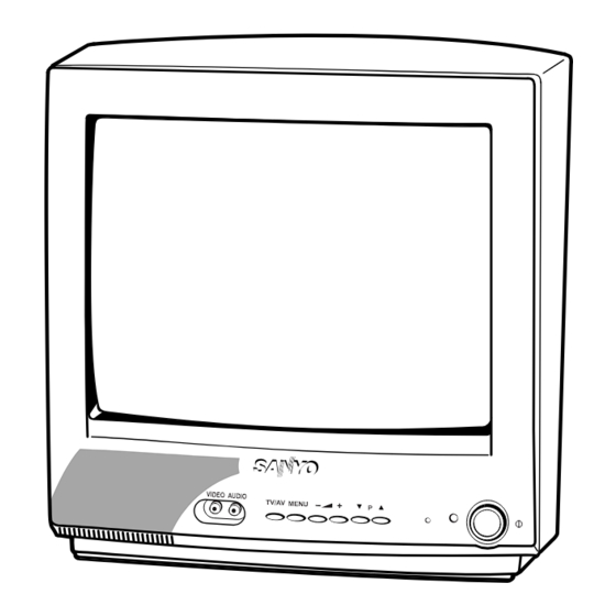
Cabinet Parts List (Model CE14SA4 & CE14SA4R) Note: Parts order must contain Service Ref. No., Part No., and descriptions. AUDIO IN VIDEO IN ANT. 75Ω AUDIO OUT VIDEO OUT TV/AV MENU TIMER TV/AV -/-- BASS SURROUND CH SCAN SWAP MENU... -
Page 18: Chassis Electrical Parts List
C5SRR Chassis Electrical Parts List (Model CE14SA4 & CE14SA4R) Product safety should be considered when a component replacement is made in any area of a receiver. Components indicated by a mark in this parts list and the circuit diagram show components whose value have special significance to product safety. - Page 19 IC MC78M05CT 405 011 8500 TR 2SC1740S-R 409 320 5700 IC UPC78M05AHF 405 011 8609 TR 2SC1740S-S IC801 Model CE14SA4: 405 012 2002 TR 2SC1815-GR 410 445 1508 IC LC863440W-50E5-TLM 405 012 2101 TR 2SC1815-O Model CE14SA4R: 405 012 2309...
- Page 20 C5SRR Ref. No. Part No. Description Ref. No. Part No. Description C172 403 215 2201 CERAMIC 0.01U K 403 049 0008 ELECT 1U M C174 403 157 1904 CERAMIC 10P D C432 403 075 7101 CERAMIC 1000P K 500V C178 404 084 8806 ELECT 1U M...
- Page 21 C5SRR Ref. No. Part No. Description Ref. No. Part No. Description 403 041 4509 ELECT 470U M R1906 401 105 2805 MT-GLAZE 2.2K JA 1/16W C661 404 084 8004 ELECT 220U M R1907 401 024 6700 CARBON 100 JA 1/6W 403 043 0202 ELECT 220U M...
- Page 22 C5SRR Ref. No. Part No. Description Ref. No. Part No. Description 402 080 2002 WIRE WOUND 1.8 KA R838 401 105 1600 MT-GLAZE 15K JA 1/16W R603 401 010 9203 CARBON 560K JA 1/2W R839 401 105 4007 MT-GLAZE 330 JA 1/16W R604 401 066 9103 OXIDE-MT...
- Page 23 C5SRR Ref. No. Part No. Description Ref. No. Part No. Description DIODE 407 013 4306 DIODE 1S2076A 407 013 7109 DIODE 1S2473 D005 407 149 0807 DIODE 1SS355-TE-17 D664 407 149 0807 DIODE 1SS355-TE-17 D1001 407 063 9603 ZENER DIODE MTZJ9.1A 407 057 9602 ZENER DIODE RD9.1EB1 D681...
- Page 24 OXIDE-MT 12K JA R725M 401 009 1508 CARBON 2.7K JA 1/2W R741 401 026 9600 CARBON 470 JA 1/6W R743 401 027 9005 CARBON 82K JA 1/6W R744 401 026 0607 CARBON 270 JA 1/6W SANYO Electric Co., Ltd. A14800/May/’04...
- Page 25 N: Metalized carbon Kind (M.carbon) 8. This circuit diagram covers a basic or representative chassis only. There S: Oxied metalized CE14SA4-00 W: Wire wounding Rated wattage (1/2W) POSISTER may be some components or partial circuit differences between the...
- Page 26 CRT BOARD (Component Location) Waveforms & Voltages (On the Main Board) R713 IC201 (IF/VIDEO/CHROMA) R719 Q701 (B-OUT) Pin-1 2.3V 2.2V 2.7V 3.2V 2.9V 2.9V 5.0V 2.5V R711 L702 Q701A 2.3V 4.3V 4.1V 4.3V 1.6V 1.7V 1.6V 8.3V 2.2V 2.1V 2.1V 2.0V 2.2V 2.7V...
Need help?
Do you have a question about the CE14SA4 and is the answer not in the manual?
Questions and answers