
Subscribe to Our Youtube Channel
Related Manuals for Trane Mitsubishi Electric TPEFYP006MS140C


Summary of Contents for Trane Mitsubishi Electric TPEFYP006MS140C
- Page 1 AIR CONDITIONERS 2022 TECHNICAL & SERVICE MANUAL Model name TPEFYP006MS140C TPEFYP018MS140C TPEFYP008MS140C TPEFYP024MS140C TPEFYP012MS140C TPEFYP015MS140C...
- Page 2 Safety Precautions Read before installation and performing electrical work Thoroughly read the following safety precautions prior to installation. Observe these safety precautions for your safety. This equipment may have adverse effects on the equipment on the same power supply system. Contact the local power authority before connecting to the system.
- Page 3 WARNING Keep electrical parts away from water. Consult your dealer or a qualified technician when moving or reinstalling the unit. Wet electrical parts pose a risk of electric shock, smoke, or fire. Improper installation may result in water leakage, electric shock, or fire.
- Page 4 Precautions for PAC-YU25HT (Optional parts) WARNING Stop the operation if any malfunction occurs. Keep the heater clean to keep the indoor unit from sucking in accumulated dust on the heater. If malfunction occurs (burning smell, etc.) stop the opera- tion and turn off the power supply. Contact your dealer or Dust particles that enter the indoor unit may cause fire.
- Page 5 HWE1833B...
-
Page 6: Table Of Contents
CONTENTS I Features [1] Features............................ 1 II Components and Functions [1] Components and Functions...................... 2 III Specfications [1] Specifications..........................5 1.Specfications .......................... 5 2.Electrical component specifications..................7 IV Outlines and Dimensions [1] Outlines and Dimensions......................8 V Wiring Diagram [1] Wiring Diagram ......................... 9 VI Refrigerant System Diagram [1] Refrigerant system diagram.................... - Page 7 HWE1833B...
-
Page 8: Features
[ I Features ] I Features [1] Features Model Cooling capacity/Heating capacity BTU/h TPEFYP006MS140C 6000/6700 1.8/2.0 TPEFYP008MS140C 8000/9000 2.3/2.6 TPEFYP012MS140C 12000/13500 3.5/4.0 TPEFYP015MS140C 15000/17000 4.4/5.0 TPEFYP018MS140C 18000/20000 5.3/5.9 TPEFYP024MS140C 24000/27000 7.0/7.9 - 1 - HWE1833B... -
Page 9: Components And Functions
[ II Components and Functions ] II Components and Functions [1] Components and Functions 1. Indoor (Main) Unit - 2 - HWE1833B... - Page 10 [ II Components and Functions ] 2. Remote Controller [TAR-40MAAU] Once the operation mode is selected, the unit will remain in the selected mode until changed. (1) Remote Controller Interface ⑤ ⑥ ④ ③ ② ① Function buttons ⑦ ⑧ ⑨...
- Page 11 [ II Components and Functions ] (2) Remote Controller Display The main display can be displayed in two different modes: “Full” and “Basic.” The factory setting is “Full.” To switch to the “Basic” mode, change the setting on the Main display setting. ▌...
-
Page 12: Specfications
[ III Specfications ] III Specfications [1] Specifications 1. Specfications Model TPEFYP006MS140C TPEFYP008MS140C TPEFYP012MS140C TPEFYP015MS140C Power source 1-phase 208/230V 60Hz Cooling capacity BTU / h 6,000 8,000 12,000 15,000 (Nominal) Power input 0.05/0.05 0.06/0.06 0.07/0.07 0.07/0.07 Current input 0.42/0.41 0.51/0.49 0.56/0.53 0.57/0.55 Heating capacity... - Page 13 [ III Specfications ] Model TPEFYP018MS140C TPEFYP024MS140C Power source 1-phase 208/230V 60Hz Cooling capacity BTU / h 18,000 24,000 (Nominal) Power input 0.09/0.09 0.12/0.12 Current input 0.74/0.70 0.98/0.93 Heating capacity BTU / h 20,000 27,000 (Nominal) Power input 0.07/0.07 0.10/0.10 Current input 0.64/0.60 0.88/0.83...
-
Page 14: Electrical Component Specifications
[ III Specfications ] 2. Electrical component specifications Component Sym- TPEFYP006MS140C TPEFYP008MS140C TPEFYP012MS140C Room temperature TH21 Resistance 0°C[32°F]/15kΩ, 10°C[50°F]/9.6kΩ, 20°C[68°F]/6.3kΩ, 25°C[77°F]/5.4kΩ, thermistor 30°C[86°F]/4.3kΩ, 40°C[104°F]/3.0kΩ Liquid pipe thermistor TH22 Resistance 0°C[32°F]/15kΩ, 10°C[50°F]/9.6kΩ, 20°C[68°F]/6.3kΩ, 25°C[77°F]/5.4kΩ, 30°C[86°F]/4.3kΩ, 40°C[104°F]/3.0kΩ Gas pipe thermistor TH23 Resistance 0°C[32°F]/15kΩ, 10°C[50°F]/9.6kΩ, 20°C[68°F]/6.3kΩ, 25°C[77°F]/5.4kΩ, 30°C[86°F]/4.3kΩ, 40°C[104°F]/3.0kΩ... -
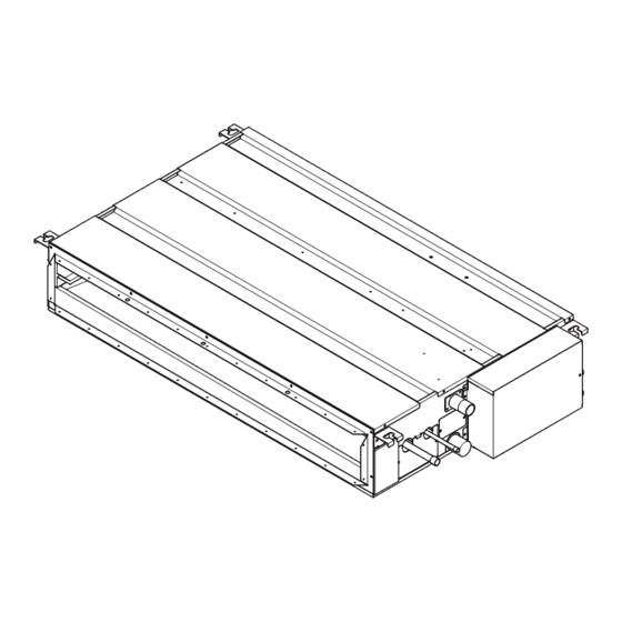
Page 15: Outlines And Dimensions
[ IV Outlines and Dimensions ] IV Outlines and Dimensions [1] Outlines and Dimensions 1. TPEFYP006, 008, 012, 015, 018, 024MS140C Unit : mm(in) - 8 - HWE1833B... -
Page 16: Wiring Diagram
[ V Wiring Diagram ] V Wiring Diagram [1] Wiring Diagram 1. TPEFYP006, 008, 012, 015, 018, 024MS140C - 9 - HWE1833B... -
Page 17: Refrigerant System Diagram
[ VI Refrigerant System Diagram ] VI Refrigerant System Diagram [1] Refrigerant system diagram Gas pipe thermistor TH23 Gas pipe Liquid pipe Brazed connections Strainer (#100 mesh) Linear expansion valve Liquid pipe thermistor TH22 Heat exchanger Room temperature thermistor TH21 mm [in.] Capacity TPEFYP006, 008, 012, 015, 018MS140C... -
Page 18: Microprocessor Control
[ VII Microprocessor Control ] VII Microprocessor Control [1] Microprocessor Control 1. Cool operation <How to operate> 1. Press POWER [ON/OFF] button. 2. Press the [F1] button to display Cool. 3. Press the [F2] or [F3] button to set the desired temperature. The set temperature changes 2°F when the [F2] or [F3] button is pressed one time. -
Page 19: Dry Operation
[ VII Microprocessor Control ] 2. Fan (1) By the remote controller setting (switch of 3 speeds+Auto) Type Fan speed notch 3 speeds + Auto type [Low], [Med], [High], [Auto] When [Auto] is set, fan speed is changed depending on the value of: Room temperature - Desired temperature 3. -
Page 20: Fan Operation
[ VII Microprocessor Control ] (2) Frozen prevention control No control function 2. Fan (1) Indoor fan operation controlled depends on the compressor conditions. Dry thermo Fan speed notch [Low] Excluding the following Stop Room temp. < 64°F [Low] Remote controller setting is not acceptable. 3. -
Page 21: Heat Operation
[ VII Microprocessor Control ] 4. Heat operation <How to operate> 1. Press POWER [ON/OFF] button. 2. Press the [F1] button to display Heat. 3. Press the [F2] or [F3] button to set the desired temperature. The set temperature changes 2°F when the [F2] or [F3] button is pressed one time. -
Page 22: Auto Operation [Automatic Cool / Heat Change Over Operation]
[ VII Microprocessor Control ] This control is same for the model without auxiliary heater. (4) Thermo OFF mode When the thermoregulating function changes to OFF, the indoor fan operates in [Extra low]. (5) Heat defrosting mode The indoor fan stops. 3. -
Page 23: When Unit Is Stopped Control Mode
[ VII Microprocessor Control ] 4. HEAT mode (1) Same control as heat operation The value "3°F" is modifiable from 1.8°F to 9°F by maintenance tool. 6. When unit is stopped control mode 1. Drain pump (1) Drain pump control The drain pump turns ON for the specified amount of time when any of the following conditions is met: 1) ON for 3 minutes after the operation mode is switched from COOL or DRY to another operation mode (FAN). - Page 24 [ VII Microprocessor Control ] Table.2 Heater OFF Heater control #B Heater OFF Inlet air temp. set temp. Inlet air temp. set temp. Heater control #A Heater ON Heater ON Inlet air temp. < set temp.-4°F Inlet air temp. < set temp.-1.8°F Set temp.
- Page 25 [ VII Microprocessor Control ] Reference (not applicable to the ducted models) Pattern NON duct unit CN4Y for FAN control (YU25) *3 DIP S/W (Indoor unit) Fan in defrost Stop (Heater ON) *3 Refer to Section 5 "Dipswitch Setting" for further information about each switch. <Image>...
- Page 26 [ VII Microprocessor Control ] 2) TPEFYP-MA143A, TPEFYP-MH142A and other models Indoor unit Outdoor unit Remote control board Relay circuit control board control board Adapter • TUHY,TURY type Dip CN24 switch SW4: 932 “ON/OFF” • TUMY series White Dip switch SW5-4 CN22 “ON/OFF”...
-
Page 27: Troubleshooting
[ VIII Troubleshooting ] VIII Troubleshooting [1] Troubleshooting 1. Check methods 1. Component and check points (1) Thermistor Room temperature thermistor (TH21) Liquid pipe thermistor (TH22) Gas pipe thermistor (TH23) Disconnect the connector and measure the resistance between terminals with a tester. (Ambient temperature 10°C - 30°C[50°F-86°F]) Normal Abnormal... - Page 28 [ VIII Troubleshooting ] 1) Summary of linear expansion valve (LEV) operation The LEV is operated by a stepping motor, which operates by receiving a pulse signal from the indoor control board. The LEV position changes in response to the pulse signal. Indoor control board and LEV connection 12VDC Brown...
- Page 29 [ VIII Troubleshooting ] 2) LEV operation Close Open Fully open valve (2000 pulses) No. of pulses Extra tightning (80 - 100 pulse) Valve opening degree When the power is turned on, a pulse signal of 2200 pulses is output (valve closure signal), to bring the valve to position A. When the valve is operating normally, it is free of vibration noise.
- Page 30 [ VIII Troubleshooting ] Symptom Checking Criteria Remedy Valve closure fail- To check the LEV on the indoor unit, check the indoor unit liquid pipe temperature Replace the LEV ure (leaky valve) that appears on the operation monitor on the outdoor unit's multi control board while if the amount of operating the indoor unit in question in the FAN mode and the other indoor units in leakage is great.
-
Page 31: Dc Fan Motor (Fan Motor/Indoor Control Board)
[ VIII Troubleshooting ] 2. DC fan motor (fan motor/indoor control board) 1. CAUTION A high voltage is applied to the connector for connection to the fan motor (CNMF). Do not unplug the connector CNMF with the unit energized to avoid damage to the indoor control board and fan motor. 2. -
Page 32: Address Switch Setting
[ VIII Troubleshooting ] 3. Address switch setting Make sure that power to the unit is turned off. 9 10 Indoor unit control board Factory setting (all models) 1. When using an ME remote controller, set the address with the rotary switches (SW11, SW12). Address setting is not required when the unit remote controller is used. -
Page 33: Voltage Test Points On The Control Board
[ VIII Troubleshooting ] 4. Voltage test points on the control board 1. TPEFYP006, 008, 012, 015, 018, 024MS140C Fuse Fuse(AC 250V 6.3A) Power supply voltage (208 - Fuse 230VAC) CN2M For M-NET transmission cable connection (24 - 30VDC) Emergency operation Capacity setting Function setting CN42... -
Page 34: Dipswitch Setting (Factory Setting)
[ VIII Troubleshooting ] 5. Dipswitch setting (Factory setting) 1. Function setting (1) SW1 Switch position Function Switch setting Active Thermistor (Intake air Built-in thermistor on the remote Indoor unit thermistor) controller Filter clogging detection Available Unavailable Filter life 2500 hr 100 hr Outdoor air intake Enabled... - Page 35 [ VIII Troubleshooting ] 1) Indoor control board Dipswitch settings must be made while the unit is stopped. Factory setting TPEFYP006MS140C TPEFYP008MS140C TPEFYP012MS140C 9 10 9 10 9 10 TPEFYP015MS140C TPEFYP018MS140C TPEFYP024MS140C 9 10 9 10 9 10 2. Capacity code setting (1) SW2 1) Indoor control board Dipswitch settings must be made while the unit is stopped.
- Page 36 [ VIII Troubleshooting ] 4. External static pressure (1) SWA, SWC 1) Address board All models Factory Pa[in.WG] setting 5[0.02] 15[0.06] 35[0.14] 50[0.20] (A) Option SWA SWC SWA SWC SWA SWC SWA SWC (B) Standard Note: Changes that are made to the dipswitches SWA and SWC immediately become effective regardless of the unit's operation status (RUN/STOP) or the remote controller status (ON/OFF).
-
Page 37: Disassembly Procedure
[ IX Disassembly Procedure ] IX Disassembly Procedure [1] Disassembly Procedure 1. Control box Exercise caution when removing heavy parts. 1. Removing the control box cover (1) Remove the two fixing screws on the cover (A) to remove Fig.1 Fig.2 - 30 - HWE1833B... -
Page 38: Thermistor (Intake Air)
[ IX Disassembly Procedure ] 2. Thermistor (Intake air) Exercise caution when removing heavy parts. 1. Remove the control box cover according to the procedure in section 1. 2. Remove the thermistor. (1) Remove the two fixing screws on the metal base (B) to re- move it. -
Page 39: Drainpan
[ IX Disassembly Procedure ] 3. Drainpan Exercise caution when removing heavy parts. 1. Removing the filter and the bottom plate (1) Push down the tab on the filter (a), and pull out the filter in the direction of the arrow 1. (2) Remove the fixing screws on the bottom plate (D), (E) to remove it. -
Page 40: Thermistor (Gas Pipe) (Liquid Pipe)
[ IX Disassembly Procedure ] 4. Thermistor (Gas pipe) (Liquid pipe) Exercise caution when removing heavy parts. 1. Remove the drain pan according to the procedure in sec- tion 3. 2. Removing the Heat exchanger cover (1) Remove the four fixing screws on the heat exchanger cov- er (F) to remove it. -
Page 41: Fan And Fan Motor
[ IX Disassembly Procedure ] 5. Fan and fan motor Exercise caution when removing heavy parts. 1. Removing the filter and the bottom plate (1) Push down the tab on the filter (a), and pull out the filter in the direction of the arrow 1. (2) Remove the fixing screws on the bottom plate (J) to re- move it. -
Page 42: Bearing
[ IX Disassembly Procedure ] 6. Bearing P015, P018, P024 models only. Exercise caution when removing heavy parts. 1. Removeing the bearing (1) Remove the two fixing screws on the bearing cover (M) to remove it. Fig.14 (2) Remove the two bearing retainer screws to remove the bearing. -
Page 43: Heat Exchanger
[ IX Disassembly Procedure ] 7. Heat exchanger Exercise caution when removing heavy parts. 1. Remove the drain pan according to the procedure in section 2. Remove the heat exchanger cover according to the proce- dure in section 4. 2. 3.
Need help?
Do you have a question about the Mitsubishi Electric TPEFYP006MS140C and is the answer not in the manual?
Questions and answers