
Related Manuals for Thor Kitchen MK07SS304-W


Summary of Contents for Thor Kitchen MK07SS304-W
- Page 1 OUTDOOR Pizza Oven Cabinet Installation Manual MODEL# MK07SS304-W IMPORTANT: Save for electrical inspector’s use. Installer: Leave installation instructions with the homeowner. Homeowner: Keep installation instructions for future reference.
- Page 2 Please keep this manual for future reference, as it contains answers to questions that you might have as you begin to cook. Thank you This manual applies to the following models’ series: Model # MK07SS304-W (Outdoor Pizza Oven Cabinet)
- Page 3 Parts Explosive Pictures...
-
Page 4: Parts List
Parts List Explosive # Part # Part Name Quantity 05.99.000119-000-A0 Chimney coping 05.19.008003-000-A0 Chimney supporting rod 22.99.009241-000-A0 Chimney pipe assembly 22.99.009239-000-A0 Pizza oven cavity 05.99.008024-000-A0 Thermometer 06.04.000377-000-A0 Mica plate 1 22.99.009243-000-A0 Pizza oven door handle assembly 20.01.008025-000-A1 Pizza oven door assembly 20.01.008022-000-A1 Beam welding assembly 20.01.008018-000-A0... - Page 5 05.99.000200-000-A0 Pizza oven brush 05.99.000201-000-A0 Large pizza oven shovel ¼” Philips thumb head screw with anti- 06.02.000093-000-A0 slip design 06.10.000042-000-A0 Philips thumb head screw 06.11.008056-000-A0 flat head screw 06.09.000099-000-A0 1/4" nut 04.01.002580-000-A0 cabinet back connecting plate 04.01.002579-000-A0 cabinet front connecting plate 06.04.000030-000-A0 ¼”...
- Page 6 Product Dimension...
- Page 7 Cabinet Installation Step 1 1. Install 2 pcs supporting legs (Part # 18) to bottom welding part (Part # 21) and adjust the supporting legs to suitable position; 2. Use 16 pcs ¼” flat Philip’s screw head (Part # 37) to connect 2 pcs fixed casters (Part # 19) and 2 pcs universal casters with brake (Part # 20) to Part #21;...
- Page 8 Step 2 1. Use 2 pcs Philips thumb head screw (Part # 38) to install Kick panel plate (Part # 17) to Part # 21; 2. Use 3 pcs ¼” flat Philip’s screw head (Part # 37) to connect left side panel (Part # 10) to Part # 21;...
- Page 9 Step 3 1. Use 4 pcs Part # 37 to connect beam welding part (Part # 24) to Part # 10 and Part # 25; 2. Use 4 pcs Part # 37 to connect top cover welding part (Part # 15) to Part # 10 and Part # 25;...
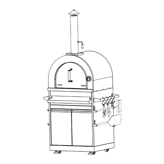
- Page 10 Step 4 1. Make sure all the connections are smooth and the design is looking like below picture.
- Page 11 Step 5 1. Use 2 pcs ¼” 14” screw (Part # 37) to go through the two holes on Pizza oven door handle assembly (Part # 67), then go through 4 pcs mica plates (Part # 6), 2 pcs ¼” flat gasket (Part # 43), 2 pcs ¼” spring gasket (Part # 44), and 2 pcs ¼”...
- Page 12 Step 6 1. Use 4 pcs ¼” Philips thumb head screw with anti-slip design (Part # 37) to put 2 pcs ash pan holder (Part # 32) to the back of Pizza oven cavity (Part # 2. One part # 32 are installed, install ash pan welding assembly (Part # 27).
- Page 13 Step 7 1. Use 1 pc ¼” nut (Part # 40) and 1 pc ¼” flat gasket (Part # 43) to connect chimney coping (Part # 1) to chimney supporting rod (Part # 2) 2. Install Part # 1 and # 2 to the top of Chimney Pipe Assembly (Part # 3); 3.
- Page 14 Step 8 1. Put 4 pcs Cordierite Brick B (Part # 28), 2 pcs Cordierite Brick A (Part # 29) and 1 pc net cover (Part # 30) inside Pizza oven Cavity (Part # 4) 2. Insert Pizza oven door assembly (Part #8) into designated position on Part # 3.
- Page 15 Step 9 1. Use 6 pcs ¼” Philips thumb head screw with anti-slip design (Part # 37) to install Pizza oven cavity (Part # 4) to Cabinet left side panel (Part # 10) and Cabinet right panel (Part # 25). Make sure the connection is smooth; 2.
- Page 16 Step 10 1. Use 2 pcs Part # 37 to connect condiment storage welding assembly (Part # 16) to front panel assembly (Part # 15); 2. Use 24 pcs Parts # 39 to install door hinge (Part # 31) Part # 22 with Part # 10, and Part # 23 with Part # 25;...
- Page 17 Detailed Installation Pictures for Door hinge is shown below:...
- Page 18 Step 11 1. Use 4 pcs Part # 37 to connect Left handle welding assembly (Part # 11) to Left side panel (Part # 10), then put S-shape pothook (Part # 12) on Part # 2. Use 8 pcs Part # 37 to connect side panel hook 1 (Part # 13) and side panel hook 2 (Part # 14) to the left panel (Part # 10);...
Need help?
Do you have a question about the MK07SS304-W and is the answer not in the manual?
Questions and answers