Advertisement
Table of Contents
- 1 Radio Transmitter/Receiver
- 2 Description of Configurable Products in Quicklink Configuration Instructions
- 3 Configuring a Function (5 Steps)
- 4 Scenario Function
- 5 Application Examples
- 6 Transform a Double Switch into a Double Two Ways Switch
- 7 Make a Group Control for “X” Motorized Shutter or Blinds (Example with 3 Motors)
- Download this manual
TR M 69 1A U
0 V 50 Hz
20 0 W AC 1 23
m W 45 °C
43 3. 5 M hz 10
LED
L
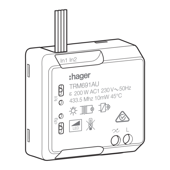
TRM691AU
Radio transmitter/receiver
2 inputs + 1 dimmer 200W
In1 In2
TRM691AU
200 W AC1 230 V 50Hz
433.5 Mhz 10mW 45°C
LED
10A
Metal surfaces in the direct vicinity of the
product (e.g. flush mounted metal boxes)
may reduce the radio range.
Avoid the use of a metal front plate for
switches in combination with flush mounted
metal boxes.
Load type
230 V
230 V
230 V
230 V
230 V
LED
Non-dimmable LED and compact fluorescent lamps are not compatible with this product.
1
- This unit is to be installed by a qualified
professional only according to the
installation standard in force in the country.
- Cut off 230V power supply to the product
z
before connection of or operation on the
inputs.
- Do not remove the insulating sleeves on
the unused input wires.
The TRM691AU is a radio transmitter/receiver,
powered in series with the load. It is used for
dimming incandescent, LV and ULV halogen, and
dimmable LED loads.
It includes:
- 2 inputs for connection of pushbuttons, switches
or other automatic control contacts.
- A dimming output (max. 200W ).
The inputs connected to the product are freely
Complies with
programmable. They can control the local output
IMDA Standards
DA101847
or other outputs.
quicklink
and operated within the same radio installation.
Caption
1 Pushbutton or switch
2 Connecting wires of the 2 inputs for a switch or
pushbutton
3 Pushbutton and feature LED T of output
4 Pushbutton and configuration LED
5 Connector block :
- L : Phase 230 V
-
: Dimming output 230 V
Do not cut the input wires, even if they are not
O
used.
Features
• 1 independent channel controlled by radio.
(output 200W AC1 230V).
• 2 inputs for contact free of potential.
L
In operation :
• Availability of output manual control by
pushbutton T
• Display of output state on LED fct (red light ON
= active output).
The specific features of each product depend on
configuration and set-up.
Learning the load type
The first time it is turned on, the product undertakes
automatic learning of the connected lamp type.
A brief flicker may be observed during this phase
(duration 2 to 3 s) after which the lamp type is
stored in the product.
After a power outage or change of lamp, the
dimmer starts a new detection.
If the user notices unsatisfactory operation, the
setting can be edited manually.
Manual setting of the load
Make 5 consecutive short presses on the dimmer
pushbutton, until the lamp is observed to flash.
Incandescent lamps
halogen lamps
Halogen ELV (12 or 24 V) via ferromagnetic transformer
Halogen ELV (12 or 24V) via electronic transformer
Dimmable LEDs
products can be configured together
R
10 ... 200 W
10 ... 200 W
10 ... 175 VA
10 ... 175 VA
3 ... 50 W
The dimmer is now in manual setting mode.
Briefly press the dimmer pushbutton to select the
desired setting: (see table below)
Note: Automatic departure from manual mode and
setting validation occur after 10 s inactivity.
Dimming
pushbutton
Number of
Number of short
blinks
presses
1x
1x
2x
2x
The lamp is lit at the minimum
level = minimum threshold setting
mode active.
Further presses of the dimming
3x
pushbutton are used to test other
levels (to perform the test in the
dark).
Saving of the minimum threshold
after 10 s inactivity
Protection against overheating and overload
The product is automatically protected against
overloads, short circuits and overheating. In the
event of overheating or overload, the available
power is automatically reduced.
Factory set-up
By default, input 1 is configured to receive a
pushbutton and to control the local dimming
output (short press = ON/OFF; maintained push
= increase/decrease with the direction changing
following each new press).
This link can be edited or deleted in configuration
mode.
A factory reset of the product reinstalls this link
O
(factory settings). Input 2 is not pre-programmed.
Factory Reset
Maintain
pushbutton down until LED cfg
R
flickers (>10s), then release. cfg LED turns OFF to
signal Factory Reset end. This operation removes
the entire product configuration in any configuration
mode.
After power switch-On or Factory Reset, wait for
15s before to do a new configuration.
These instructions for use form an integral part
O
of the product and must be retained by the end
user.
Technical characteristics
230 V
Supply voltage
240 V
Product consumption
100mW
Upstream protection:
10A
circuit breaker
Transmission frequency/
433,05 - 434,79 MHz
Emission power
10 mW
Dimensions
40 x 40 x 18 mm
Max. connection
< 10 m
distance per input
Minimum contacts
50 ms
closing time
Degree of protection
IP 20
Operating altitude
≤ 2000 m
Pollution degree
2
Overvoltage category
III
Operating temperature
-15 °C —> + 45 °C
Storage temperature
- 20°C —> + 70 °C
Receiver category 2 / Transmitter duty cycle
<10%
Electric connection:
0,5 mm
0,5 mm
Setting type
Automatic
detection mode
(default value)
Standard LED
mode
+10 %-15% 50 Hz
+6%/-6% 50 Hz
2
2
—> 1,5 mm
2
2
—> 2,5 mm
6LE005076D
Advertisement
Table of Contents

Related Manuals for hager TRM691AU


Summary of Contents for hager TRM691AU
- Page 1 Number of Setting type Number of short blinks presses The TRM691AU is a radio transmitter/receiver, TR M 69 1A U 0 V 50 Hz Automatic 20 0 W AC 1 23 powered in series with the load. It is used for m W 45 °C...
- Page 2 ON/OFF (switch) (switch) Etiquette fonctions Priority ON Up priority å Priority OFF Down priority Hager Controls hereby declares that the radio transmitter/receiver complies with the 2014/53/ EU directive. The CE declaration can be consulted Clear Clear Clear on the site: www.hager.com...
- Page 3 Configuring a function (5 steps) Action Result Starting configuration Give a short press on the button of • LEDs of all the the transmitter or transmitter/receiver. In1 In2 In1 In2 In1 In2 In1 In2 In1 In2 In1 In2 receivers and the emitter come on.
- Page 4 Scenario function Ex. e.g. TV scenario The scenario control is used to activate the desired ambience directly, by simultaneously acting on various types of receiver (e.g. TV scenario: turn off the ceiling lights + switch on appliances + lower the shutters for the living room).
- Page 5 702AU (Short push = ON/OFF; maintained push = increase/decrease) and connect it to the input one (white and yellow wire) of the TRM691AU. Now the product is working with dimming function (factory set-up,) if you want the internally link can be edited, deleted or modified, see configuration.
- Page 6 692AU 692AU 692AU 702AU TRM702AU In1 In2 TRM702A RF1.M EC/EP 868 MHz IP30 In1 In2 TRM702A RF1.M EC/EP 868 MHz IP30 702AU Hager Controls S.A.S., 33 rue Saint-Nicolas, B.P. 10140, 67703 SAVERNE CEDEX, France - www.hager.com Hager 09.18 - 6LE005076D...
Need help?
Do you have a question about the TRM691AU and is the answer not in the manual?
Questions and answers