
Related Manuals for Mini-Circuits U2C-1SP2T-63VH


Summary of Contents for Mini-Circuits U2C-1SP2T-63VH
- Page 1 User Guide Solid-State Switch Modules AN-49-012 © 2023 Mini-Circuits Page 1 Rev. H | ECO-018898 | 21-Aug-2023...
-
Page 2: Table Of Contents
1.3. Warranty & RMA Returns ............................... 4 1.4. End of Life ....................................4 1.5. Definitions ....................................4 2 - About Mini-Circuits Solid-State Switch Modules ............5 2.1. Introduction .................................... 5 2.2. Key Features .................................... 5 2.3. Intended Applications ................................5 2.4. - Page 3 Table of Contents (continued) 5 - Using Mini-Circuits’ GUI ....................16 5.1. Getting Started ..................................16 5.1.1. USB Control ................................... 16 5.1.2. Ethernet Control ................................17 5.2. Main Screen Operation ................................. 19 5.3. Sequence Mode ..................................20 5.3.1. Sequence Setup ................................20 5.3.2.
-
Page 4: General Information
In the event that a return to the factory is necessary, Mini-Circuits will provide an RMA number and full return instructions. -
Page 5: About Mini-Circuits Solid-State Switch Modules
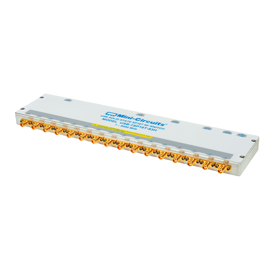
2.1. Introduction Mini-Circuits has developed a series of solid-state USB/Ethernet RF switch modules in rugged, low-profile cases. Switch models are available for a broad range of applications in frequencies from DC to 67 GHz, configurations from SPDT up to SP16T, and multiple switches integrated within a single package. -
Page 6: Model Selection Guide
For detailed model performance, data and graphs, outline drawing, ordering information and environmental specifications click on the model part number. 2.5. Environmental Specifications Mini-Circuits’ solid-state switch models are intended for operation in office, laboratory, or production test environments. Do not use in any condition which exceeds the published environmental specifications. Condition... -
Page 7: Supported Software Environments
2.6. Supported Software Environments Mini-Circuits’ solid-state switches have been tested in the following operating systems: 32-bit systems: Windows 7 or later. • • 64-bit systems: Windows 7 or later; Linux. Custom automation programs can be created in most modern programming environments, including Python, C#, LabVIEW, MatLab and more. -
Page 8: Accessories And Options
Do not allow any liquid ingress into the case or connectors. 2.10. Safety & Precautions Mini-Circuits’ solid-state switch models contain no user serviceable parts and should not be opened. Discontinue use and contact Mini-Circuits in the event of visible damage to any parts. -
Page 9: Software Setup
3 - Software Setup 3.1. System Requirements The minimum requirements for installation of the “Mini-Circuits Solid-State Switch” software package and API on the host PC are: Microsoft Windows 7 or later (32- or 64-bit). • • Intel i3 or equivalent (recommended). - Page 10 Click Yes to accept the license agreement. • Click Exit on the final window confirming that installation completed successfully. In the event of any issues with installation, please contact testsolutions@minicircuits.com for support. AN-49-012 © 2023 Mini-Circuits Page 10 Rev. H | ECO-018898 | 21-Aug-2023...
-
Page 11: Hardware Setup
• Connect 5V power either using a power adaptor such as USB-AC/DC-5+ connected to the USB port, or by supplying power to pin #1 of the D-Sub connector. AN-49-012 © 2023 Mini-Circuits Page 11 Rev. H | ECO-018898 | 21-Aug-2023... -
Page 12: I 2 C Control (U2C Series)
Power to the switch can be provided either via the I C port (see model datasheet for details) or via the USB port through a • USB device or a power adaptor such as USB-AC/DC-5+. AN-49-012 © 2023 Mini-Circuits Page 12 Rev. H | ECO-018898 | 21-Aug-2023... -
Page 13: Spi Control (U2C-1Sp2T-63Vh Only)
4.5. SPI Control (U2C-1SP2T-63VH only) The serial interface requires a full byte to be sent to each unit, although only the two LSB (least significant bits) affect the state of the switch. The control byte is loaded in a serial-in, parallel-out shift register buffered by a transparent latch. -
Page 14: Daisy-Chain Control
The serial master/slave bus allows connecting modules of different types to the same daisy-chain as long as they all support Mini-Circuits’ dynamic addressing setup. To add a new module, simply connect it to the daisy-chain and refresh the address listing – no need to reset any of the existing modules or assign addresses manually. -
Page 15: Daisy-Chain Setup Instructions
To add additional units to the daisy chain, repeat step 6 from the last unit connected to a power supply, then connect the additional units with serial control cables. When done, click on the network reconnect button in the GUI (shown below) AN-49-012 © 2023 Mini-Circuits Page 15... -
Page 16: Using Mini-Circuits' Gui
Windows GUI program to control the model manually. 5.1. Getting Started To start the program, use the Start menu or navigate to the location the “Mini-Circuits Solid-State Switch Controller” software was installed in and run the program. -
Page 17: Ethernet Control
To use Ethernet control with a supporting unit, either enter its IP address on the startup screen (ports for HTTP/Telnet/SSH would also be required if using non-default ports) or click on the search icon next to it to find all Mini-Circuits switch models connected to the network. - Page 18 Implement a Get/Post HTTP function in your selected application (for HTTP). • Establish a Telnet connection. A full list of the possible commands and queries is available in Mini-Circuits Programming handbook, and in a text file on the downloaded software, in the Ethernet directory. AN-49-012 © 2023 Mini-Circuits Page 18 Rev.
-
Page 19: Main Screen Operation
Opens sequence mode window to set sequence of timed states (see section 5.3). Mode Control Displays the control method status chosen to operate the switch unit. method Ethernet Opens the dedicated Ethernet configuration screen (see section 5.4.5). configuration AN-49-012 © 2023 Mini-Circuits Page 19 Rev. H | ECO-018898 | 21-Aug-2023... -
Page 20: Sequence Mode
To delete a line, click on the relevant step number and press the Delete button on your keyboard. • • To run only a single step, double-click on the number of that step. AN-49-012 © 2023 Mini-Circuits Page 20 Rev. H | ECO-018898 | 21-Aug-2023... - Page 21 Number of cycles to run, can be set from 1 to 65535. Cycles If “Run continuously” is selected the sequence will keep repeating until stopped. Run / Start/stop running the sequence with the current settings. Stop AN-49-012 © 2023 Mini-Circuits Page 21 Rev. H | ECO-018898 | 21-Aug-2023...
-
Page 22: High-Speed Mode
All units No delay 0.6 µs eSB-1SP4T-A673 All units No delay 0.6 µs RCS-1SP2T-A673 All units No delay 0.6 µs USB-1SP2T-673 All units No delay 5 µs AN-49-012 © 2023 Mini-Circuits Page 22 Rev. H | ECO-018898 | 21-Aug-2023... -
Page 23: Typical Transition Speed Plots
The below graphs show the typical transition time (10% / 90% signal amplitude) for selected models at different dwell times. This is the time during which the signal path is interrupted, and thus excludes communication and processing delays: Figure 5.3.3.a: U2C-1SP2T-63VH with dwell time 5 µs Figure 5.3.3.b: USB-1SP16T-83H Port 1-Port 16 with dwell time 15 µs... - Page 24 Δx = 171 ns Δx = 115 ns Figure 5.3.3.g: USB-1SP2T-A44 Port1-Port2 with dwell time 12 µs Ax = 68.3163 µs Bx = 68.3246 µs Δx = 8.3 ns AN-49-012 © 2023 Mini-Circuits Page 24 Rev. H | ECO-018898 | 21-Aug-2023...
-
Page 25: Ethernet Configuration
5.4.1. Default IP Configuration Mini-Circuits’ models ship from the factory with DHCP enabled by default so in most cases an IP address will be assigned automatically when the device is connected to the network. Once a valid IP address has been assigned and identified it can be re- configured via the Ethernet connection (for example, to set a static IP configuration) using our GUI, Ethernet configuration tool, or the programming API. -
Page 26: Ethernet Settings Screen
Note: • It is not advised to set the HTTP, Telnet, and SSH ports to use the same port. Figure 5.4.5: Ethernet Settings screen (showing factory default state) AN-49-012 © 2023 Mini-Circuits Page 26 Rev. H | ECO-018898 | 21-Aug-2023... - Page 27 A short list of useful HTTP commands. For more programming help, refer to the programming examples manual. Help Short helpful information on the window and how to use it. AN-49-012 © 2023 Mini-Circuits Page 27 Rev. H | ECO-018898 | 21-Aug-2023...
-
Page 28: Ethernet Configuration Tool
5.4.6. Ethernet Configuration Tool The Ethernet configuration can also be changed via Ethernet control. To make changing the Ethernet configuration easier for users operating in a non-Windows environment or otherwise can’t use the provided GUI, Mini-Circuits created the Ethernet configuration tool. -
Page 29: Firmware Update
To start the upgrade process, follow the below instructions carefully: • Connect only the unit to be upgraded to the PC via USB (see section 5.1.1) and start Mini-Circuits’ Solid State Switch GUI program. After selecting USB connection, click the (fw) indicator on the main screen (above the master unit’s serial number display). - Page 30 Exit to cancel the process. • Navigate to the location of the firmware .hex file you received from Mini-Circuits’ Test Solutions and chose it. The selected file should then be installed on the unit with the process taking up to a minute.
-
Page 31: Firmware Recovery
• • Start Mini-Circuits’ Solid State Switch GUI program and allow it time to attempt and establish a connection with the unit. • If the connection attempt has failed, an alert would appear advising the user of a corrupt firmware. -
Page 32: Recovery Steps (Rcs Models)
Follow the below recovery steps for RCS series switch models only: • Connect the unit to the PC via USB. Navigate to the directory where Mini-Circuits’ Solid State Switch GUI has been installed. • Locate and run the “UpgradeFirmware.exe” utility program. -
Page 33: Revision History
Revision OR (Aug 31, 2017): Initial revision of the user guide. • Revision A (Jun 05, 2018): • Added models: USB-1SP16T-83H, U2C-1SP4T-63H, U2C-1SP2T-63VH. Added descriptions of SPI and TTL control methods. • Revision B (Jan 10, 2019): • Added model: USB-2SP4T-63H. -
Page 34: Contact
This document is owned by Mini-Circuits and is protected by copyright, trademark and other intellectual property laws. The information herein is provided by Mini-Circuits as an accommodation to our customers and may be used only to promote and accompany the purchase of Mini-Circuits’ parts. This guide may not be reproduced, modified, distributed, published, stored in an electronic database, or transmitted and the information contained herein may not be exploited in any form or by any means, without prior written permission from Mini-Circuits.
Need help?
Do you have a question about the U2C-1SP2T-63VH and is the answer not in the manual?
Questions and answers