Advertisement
Quick Links
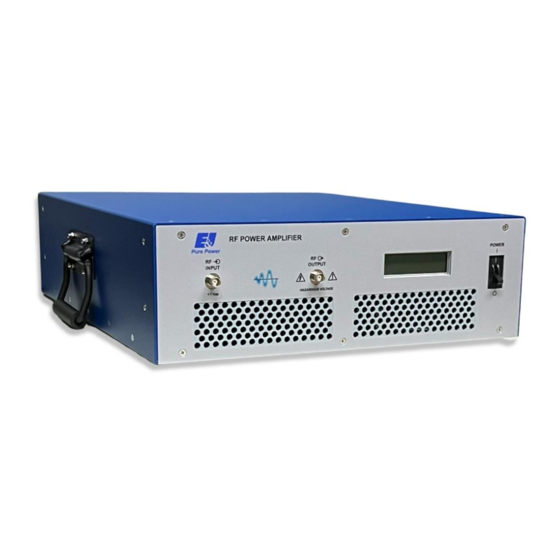
E&I A075
Broadband Power Amplifier
HIGH RF VOLTAGES MAY BE PRESENT AT THE OUTPUT OF THIS UNIT. All
operating personnel should use extreme caution in handling these voltages and be
thoroughly familiar with this manual.
Do not attempt to operate this unit prior to reading this manual.
The material contained in this document is the property of Electronics & Innovation Ltd., it is subject to
change without notice.
October 2023
Revision E
1
Advertisement

Related Manuals for Electronics & Innovation A075


Summary of Contents for Electronics & Innovation A075
- Page 1 E&I A075 Broadband Power Amplifier HIGH RF VOLTAGES MAY BE PRESENT AT THE OUTPUT OF THIS UNIT. All operating personnel should use extreme caution in handling these voltages and be thoroughly familiar with this manual. Do not attempt to operate this unit prior to reading this manual.
-
Page 2: Table Of Contents
Warranty Electronics & Innovation Ltd., (hereafter E&I) warrants for the period of three years from the date of original delivery, each unit to be free of defects in materials and workmanship. For the period of 36 months E&I will, at its option, repair or replace defective parts so as to render the unit fully operational such that it performs according to the original specifications;... -
Page 3: Chapter 1 General Information
Chapter 1 Introduction The A 075 is a broadband solid state amplifier covering the frequency spectrum from 300 KHz to 35 MHz. It is rated at 75 watts of RF power with low harmonic and intermodulation distortion. Over 150 watts of saturated power can be produced with increased distortion products. -
Page 4: Chapter 2 Operation
Table 1-1. SPECIFICATIONS FREQUENCY COVERAGE: 300 kHz to 35 MHz GAIN: 50 dB min, ±1.5 variation CLASS A LINEAR OUTPUT: 75 Watts P1dB HARMONIC DISTORTION: < -25 dBc at 75 watts output. 150W Min. from 300kHz - 4MHz; SATURATED RF POWER OUTPUT: 100W Min. - Page 5 2.2 RACK INSTALLATION This unit is 3U high, 16.5” width. With the handles removed it will fit into a standard rack. 2.2.1 Mains Voltage The unit accommodates AC line voltages from 100 TO 240 VAC 47 – 63 Hz 2.3 OPERATION A line cord is supplied to form a connection between the mains supply and the rear of the unit.
- Page 6 • PSU fault (internal fault in the main switching power supply) In the event of a fault, the unit may be reset by cycling the power. In the case over an over temp fault, ensure that the air inlet and out let are not restricted. If the fault persists, please contact Field Service.
-
Page 7: Technical Information
In the default state, the RS-232 port will echo the same information sent to the front panel LCD display, allowing a running datalog to be stored to disk using the capture feature of the terminal program. Single character commands can be sent to the amplifier to achieve the following: "1"... -
Page 8: Maintenance
The switch mode power supply unit provides a 48 VDC 24 ampere source. The power supply also has a 5 VDC output which feeds the control board. 110VAC_line 110VAC_neutral earth_gnd AC In +24V_f an SELV 5V ret +48_ in SELV 5V Inhibit RS232 +24V... - Page 9 Performance limits quoted are for guidance only and should not be taken for guaranteed performance specifications unless they are also quoted in the Specification Section 1.2. 4.2 PERFORMANCE CHECKS To determine the amplifier’s performance carry out the following procedure. 4.2.1 Initial Check The following check can be made after repair and adjustments or whenever the condition of the unit is in question.
- Page 10 4.3.1 Measurement of Gain Equipment Required (or equivalent): Osilloscope - Tektronix T921 Sweep/Generator - HP8601A Signal Generator - Exact Model 7060 50 ohm Detector - Wavetek D151 Attenuator, 30 dB, 500 Watts Bird Figure 4-1. Gain Measurement 2. Connect the equipment as shown in Figure 4-1, then proceed as follows: Set the oscilloscope to DC, Time/cm to Ext.
- Page 11 step attenuator (CCW) so that the output is reduced by 50 dB. Reconnect the A 075 into the test set-up of Figure 4-1. Place the A 075 power switch to the "ON" position. Observe the gain versus frequency sweep on the oscilloscope. •...
-
Page 12: Chapter 5 Safety
frequency band of 300 KHz to 35 MHz. An indicated power output of 75W should be maintained during this operation. PACKAGING FOR RESHIPMENT In the event of the equipment being returned for servicing it should be packed in the original shipping carton and packing material. If this is not available, wrap the instrument in heavy paper or plastic and place in a rigid outer box of wood, fiberboard or very strong corrugated cardboard.
Need help?
Do you have a question about the A075 and is the answer not in the manual?
Questions and answers