Advertisement
Quick Links
TMG Corporate Website
Disclaimer:
All trademarks appearing within this PDF are trademarks of their respective owners.
Form 080/01
Complimentary Reference Material
This PDF has been made available as a complimentary service for you to assist in
evaluating this model for your testing requirements.
TMG offers a wide range of test equipment solutions, from renting short to long
term, buying refurbished and purchasing new. Financing options, such as
Financial Rental, and Leasing are also available on application.
TMG will assist if you are unsure whether this model will suit your requirements.
Call TMG if you need to organise repair and/or calibrate your unit.
If you click on the "Click-to-Call" logo below, you can all us for FREE!
TMG Products Website
Advertisement

Related Manuals for Electronics & Innovation 403LA


Summary of Contents for Electronics & Innovation 403LA
- Page 1 Complimentary Reference Material This PDF has been made available as a complimentary service for you to assist in evaluating this model for your testing requirements. TMG offers a wide range of test equipment solutions, from renting short to long term, buying refurbished and purchasing new. Financing options, such as Financial Rental, and Leasing are also available on application.
- Page 2 403LA Broadband Power Amplifier HIGH RF VOLTAGES MAY BE PRESENT AT THE OUTPUT OF THIS UNIT. All operating personnel should use extreme caution in handling these voltages and be thoroughly familiar with this manual. Do not attempt to operate this unit prior to reading this manual.
- Page 3 Warranty Electronics & Innovation Ltd., (hereafter E&I) warrants for the period of one year from the date of original delivery, each unit to be free of defects in materials and workmanship. For the period of 12 months E&I will, at its option, repair or replace defective parts so as to render the unit fully operational such that it performs according to the original specifications;...
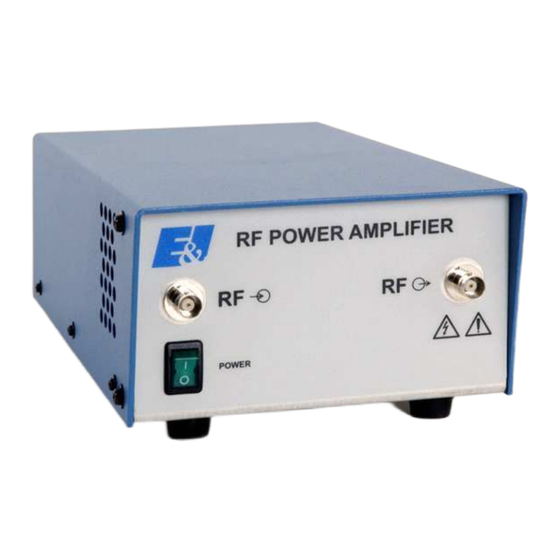
- Page 4 3W of linear power output when driven by any laboratory signal or sweep generator from 0.15 to 300 MHz An ultra linear Class A design, the 403LA will "boost" the output of any signal source by at least a flat 37 dB (±1 dB) and provide its full forward output power into any load impedance (from an open to a short circuit).
- Page 5 Adaptors provided Chapter 2 Operation 2.1 INTRODUCTION The E&I 403LA RF amplifier is used to increase the RF output level of signal sources in the 0.15 to 300 MHz range. No tuning or any other form of adjustment is required.
- Page 6 Rack Installation For standard 19" rack installations, rack mounting brackets are supplied with the unit. Remove the two M4 Phillips screws on each side of the cover nearest the front panel. Either bracket may be used on the right or left side. Attach the rack mounting brackets firmly using the hardware removed above.
- Page 7 Connect power supply. Switch on power and observe that the switch illuminates. (ii) Connect the output of the 403LA amplifier to 20 dB attenuator. (iii) Connect a calorimetric power meter (HP434 or equivalent) to the output of the attenuator.
- Page 8 Chapter 4 Maintenance Introduction The E&I 403LA RF amplifier requires no periodic maintenance. The instrument is unconditionally stable and is fail safe under all load conditions. Damages can only be externally caused by an input signal in excess of the specified IV RMS maximum.
- Page 9 Access and Layout NB: Removal of the cover voids the warranty! The E&I Model 403LA amplifier is housed in an aluminum chassis. A block diagram schematic is illustrated in figure 4. The cover can be removed by releasing the 6 M3 screws on the side of the unit.
- Page 10 The Amplifier Module The power amplifier module is mounted on the RF heat sink. To remove this module, the RF heat sink must be demounted from the chassis. To demount the heat sink, unplug the wire from the power supply module. Remove the coaxial cables connecting the RF input and output to the front panel connectors.
- Page 11 Figure 2 Harmonic Measurement Power Meter Spectrum Analyzer Sweep Generator 150 KHz – 300 MHz 20 dB RF Output Attenuator Figure 3 Block Diagram The material contained in this document is the property of Electronics & Innovation Ltd., it is subject to change without notice.
Need help?
Do you have a question about the 403LA and is the answer not in the manual?
Questions and answers