Table of Contents
Advertisement
Quick Links
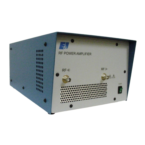
411LA
Broadband Power Amplifier
HIGH RF VOLTAGES MAY BE PRESENT AT THE OUTPUT OF THIS UNIT. All
operating personnel should use extreme caution in handling these voltages and be
thoroughly familiar with this manual.
Do not attempt to operate this unit prior to reading this manual.
The material contained in this document is the property of Electronics & Innovation Ltd., it is subject
to change without notice.
August 2012
Page 1 of 12
Revision C
Advertisement
Table of Contents

Related Manuals for Electronics & Innovation 411LA


Summary of Contents for Electronics & Innovation 411LA
- Page 1 411LA Broadband Power Amplifier HIGH RF VOLTAGES MAY BE PRESENT AT THE OUTPUT OF THIS UNIT. All operating personnel should use extreme caution in handling these voltages and be thoroughly familiar with this manual. Do not attempt to operate this unit prior to reading this manual.
-
Page 2: Chapter 1 Introduction
Chapter 1 Introduction Introduction The E&I Model 411LA is an all solid state amplifier which has a flat frequency response from 150 kHz to 300 MHz. It provides up to 10W of linear power with low harmonic and intermodulation distortion. Gain is 40 dB nominal, with variation of less than +/-2.5 dB over the entire frequency range. -
Page 3: Chapter 2 Operation
Chapter 2 Operation 2.1 Introduction The E&I 411LA RF amplifier is used to increase the RF output level of signal sources in the 0.15 to 300 MHz range. No tuning or any other form of adjustment is required. Mains Voltage Setting The unit automatically adjusts to accommodate the available AC line voltage. -
Page 4: Chapter 3 Technical Description
Chapter 3 Technical Description 3.1 GENERAL DESCRIPTION The E&I Model 411LA is a linear Class A amplifier capable of increasing the output of any signal generator, frequency synthesizer, sweep generator or laboratory signal source from 150 kHz to 300 MHz. The Model 411LA is completely protected against damage due to load mismatch provided that the input RF level does not exceed 1 VRMS or 1.4V peak. - Page 5 RF voltmeter. Precautions The input and output of the Model 411LA should not be connected together. This will cause oscillation and may damage the input preamplifier. When the input signal voltage of the signal source is unknown, insert an attenuator between it and the Model 411LA input.
- Page 6 (vi) Adjust the input CW signal to any frequency between 1 and 300MHz for 10W output. If you can not attain RF power, verify that: The mains fuse is correctly selected and not blown The switch is illuminated. If the mains fuse is not blown but you are still unable to get any RF power, either return the unit to E&I for repair or proceed to chapter 4.
-
Page 7: Chapter 4 Maintenance
NB: Removal of the cover voids the warranty! The E&I Model 411LA amplifier is housed in an aluminum chassis. A block diagram schematic is illustrated in figure 4. The cover can be removed by releasing the 6 M3 screws on the side of the unit. -
Page 8: Chapter 5 Safety
Only use the AC cord provided or equivalent. Ensure that the mains outlet is properly grounded. Appendix: Figures Figure 1 411LA Specifications Figure 2 Front and Rear View Figure 3 Gain Test Set-Up Figure 4... - Page 9 Figure 1: 411LA Specification: Frequency Coverage: 150 kHz to 300 MHz Gain: 40 dB Gain Variation: ±2.5 dB Maximum Class A Linear Output: All harmonics more than 22 dB below main signal at 10W output; lower at Harmonic Distortion: reduced power output.
- Page 10 The material contained in this document is the property of Electronics & Innovation Ltd., it is subject to change without notice. August 2012 Revision C...
- Page 11 Figure 5 Power Power Meter Meter Sweep Generator 150 KHz – 300 20 dB Attenuator Output Figure 4 Power Spectrum Meter Analyzer Sweep Generator 150 KHz – 300 20 dB Attenuator Output The material contained in this document is the property of Electronics & Innovation Ltd., it is subject to change without notice.
- Page 12 +34dBm +24V 10W_VHF_amp VHF_driver PS_24V 50 ohm 100W Title 411LA RF Amp Size Document Number 411LA-SCH-01 Date: Tuesday, July 05, 2005 Sheet The material contained in this document is the property of Electronics & Innovation Ltd., it is subject to change without notice.
Need help?
Do you have a question about the 411LA and is the answer not in the manual?
Questions and answers