Table of Contents

Related Manuals for LANGER EMV-Technik NNB 21


Summary of Contents for LANGER EMV-Technik NNB 21
- Page 1 User Manual NNB 21 set Line-impedance Stabilization Network Measurement of conducted disturbance emissions Copyright (C) Dipl.- Ing. Gunter Langer Nöthnitzer Hang 31 01728 Bannewitz June 2023 2023.06.02_NNB 21 set_user manual...
- Page 2 LANGER DE-01728 Bannewitz NNB 21 set mail@langer-emv.de EMV-Technik www.langer-emv.com Content Page Declaration of Conformity General Information Storing the User Manual Reading and Understanding the Manual Local Safety and Accident Prevention Regulations Images Limitations of Liability Errors and Omissions Copyright Scope of Delivery...
- Page 3 Langer EMV-Technik GmbH Noethnitzer Hang 31 01728 Bannewitz Germany Langer EMV-Technik GmbH hereby affirms, that the product specified below NNB 21 set with NNB 21 Line-impedance Stabilization Network agrees with the regulations of EC guidelines: - Low Voltage Directive 2014/35/EU...
- Page 4 2 General Information 2.1 Storing the User Manual This user manual provides the basis for the safe and efficient use of the NNB 21 set. It must be kept handy and easily accessible for the user. 2.2 Reading and Understanding the Manual Read and understand the manual and observe the instructions carefully before using the product.
- Page 5 User manual NNB 21 m System Case NNB 21 case Important: The scope of delivery may differ depending on the respective order. Figure 1: NNB 21 set case 4 Technical Parameters RF-Path Measuring channels 2, one path can be deactivated 100 kHz –...
- Page 6 - Before operating a measuring station with a product of Langer EMV-Technik GmbH, carry out a visual inspection. Damaged connecting cables must be replaced before operation. - The product of Langer EMV-Technik GmbH may only be used for applications for which it is intended. Any other use is not permitted.
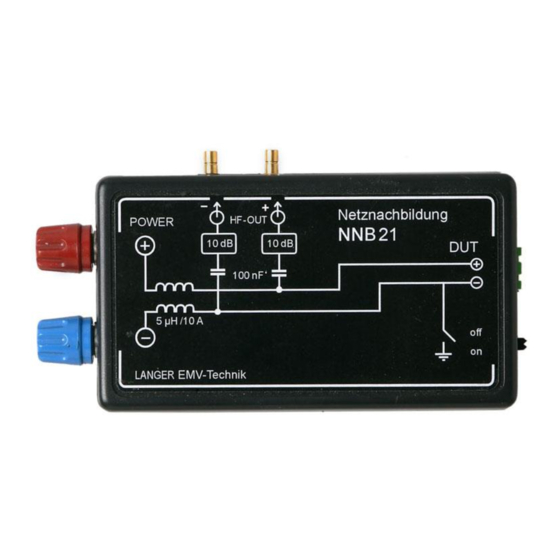
- Page 7 for measurements with an upper limit frequency of 1 GHz less than 5 cm, - If both connections of the NNB 21 are used to supply the DUT and the GND switch is open, the NNB 21 measures the total current (common mode) of both lines.
- Page 8 This document may not be copied, reproduced or electronically processed, either in its entirety or in part, without the prior written permission of Langer EMV-Technik GmbH. The management of Langer EMV-Technik GmbH assumes no liability for damage that may arise from using this printed information.
Need help?
Do you have a question about the NNB 21 and is the answer not in the manual?
Questions and answers