
Subscribe to Our Youtube Channel
Related Manuals for Intesis INMBSMEB0200100


Summary of Contents for Intesis INMBSMEB0200100
- Page 1 ENGLISH M-BUS to Modbus TCP Server Gateway USER MANUAL Version 1.0.1 Publication date 2023-08-08...
- Page 2 Copyright © 2023 Intesis Disclaimer The information in this document is for informational purposes only. Please inform HMS Networks of any inaccuracies or omissions found in this document. HMS Networks disclaims any responsibility or liability for any errors that may appear in this document.
-
Page 3: Table Of Contents
7.6. Modbus Server Interface Points Definition ................15 8. Setup Process with the Configuration Tool .................. 16 8.1. Prerequisites ........................16 8.2. Intesis MAPS Configuration and Monitoring Tool ..............16 8.2.1. Introduction ......................16 8.2.2. Create a New Project from a Template ................. 17 8.2.3. -
Page 4: Description And Order Codes
M-BUS to Modbus TCP Server Gateway 1. Description and Order Codes INMBSMEBxxx0100 Protocol Translator Gateway M-Bus to Modbus TCP server gateway ORDER CODE LEGACY ORDER CODE INMBSMEB0200100 IBMBSMEB0200100 INMBSMEB0500100 IBMBSMEB0500100 NOTICE The order code may vary depending on the product seller and the buyer's location. -
Page 5: Gateway Capacity
M-BUS to Modbus TCP Server Gateway Gateway Capacity 2. Gateway Capacity Element INMBSMEB0200100 INMBSMEB0500100 Notes Those supporting the Modbus protocol. Type of Modbus client Modbus TCP devices Communication over TCP/IP. Number of Modbus client Up to five TCP connections Number of Modbus client devices supported by the gateway. -
Page 6: General Information
3. General Information 3.1. Intended Use of the User Manual This manual contains the main features of this Intesis gateway and the instructions for its appropriate installation, configuration, and operation. The contents of this manual should be brought to the attention of any person who installs, configures, or operates this gateway or any associated equipment. - Page 7 M-BUS to Modbus TCP Server Gateway Admonition Messages and Symbols NOTE Additional information which may facilitate installation and/or operation. Helpful advice and suggestions. NOTICE Remarkable Information. Page 4 of 20 USER MANUAL Version 1.0.1...
-
Page 8: Overview
M-Bus device was part of the Modbus installation. For this, the Intesis gateway acts as a Modbus TCP server device in its Modbus interface, allowing it to read/write points from the Modbus client device(s). From the M-Bus point of view, the gateway acts as an M-Bus level converter and Master device (EN-1434-3). -
Page 9: Gateway General Functionality
M-BUS to Modbus TCP Server Gateway Gateway General Functionality 4.3. Gateway General Functionality This gateway acts as a server on its Modbus side and as a master on its M-Bus interface, thus allowing the integration of M-Bus devices into a Modbus system. The gateway is continuously polling the devices (together or individually), storing in its memory the current status of every signal you want to track, and serving this data to the installation when requested. -
Page 10: Hardware
Hardware M-BUS to Modbus TCP Server Gateway 5. Hardware 5.1. Mounting IMPORTANT Before mounting, please ensure that the chosen installation place preserves the gateway from direct solar radiation, water, high relative humidity, or dust. NOTE Mount the gateway on a wall or over a DIN rail. DIN rail mounting inside a grounded metallic cabinet is recommended. -
Page 11: Connection
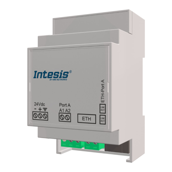
M-BUS to Modbus TCP Server Gateway Connection 5.2. Connection CAUTION Disconnect all systems from the power source before manipulating and connecting them to the gateway. IMPORTANT Keep communication cables away from power and ground wires. 5.2.1. Gateway Connectors Figure 2. General view of all gateway connectors 1. - Page 12 Connection M-BUS to Modbus TCP Server Gateway IMPORTANT Use solid or stranded wires (twisted or with ferrule). Wire cross-section/gauge for all wire connectors: • One core: 0.2 to 2.5 mm (24 to 11 AWG). • Two cores: 0.2 to 1.5mm (24 to 15 AWG).
-
Page 13: Common Connections
• Use SELV-rated NEC class 2 or limited power source (LPS) power supply. • Connect the gateway's ground terminal to the installation grounding. • A wrong connection may cause earth loops that can damage the Intesis gateway and/or any other system equipment. -
Page 14: Technical Specifications
Technical Specifications M-BUS to Modbus TCP Server Gateway 5.3. Technical Specifications Plastic, type PC (UL 94 V-0). Color: Light Grey. RAL 7035 Case Net dimensions (dxwxh): 93 x 53 x 58 mm / 3.6 x 2.1 x 2.3" Recommended space for installation (dxwxh): 100 x 60 x 70 mm / 3.9 x 2.4 x 2.7" Wall Mounting DIN rail (recommended mounting) EN60715 TH35... -
Page 15: Dimensions
M-BUS to Modbus TCP Server Gateway Dimensions 5.4. Dimensions • Net dimensions (DxWxH) Millimeters: 93 x 53 x 58 mm Inches: 3.6 x 2.1 x 2.3" • Clear space for installation (DxWxH) Millimeters: 100 x 60 x 70 mm Inches: 3.9 x 2.4 x 2.7" Page 12 of 20 USER MANUAL Version 1.0.1... -
Page 16: M-Bus System
Intesis MAPS configuration tool. USER MANUAL Version 1.0.1... -
Page 17: Modbus System
7.2. ModBus Interface The Intesis gateway acts as a server device in its Modbus interface; the interface for this model is the Ethernet port. To access the points and resources of the gateway from a Modbus client device, you must specify the Modbus register addresses configured inside the gateway as those configured inside the gateway corresponding to the signals of the field device protocol. -
Page 18: Address Map
Modbus register address. 7.6. Modbus Server Interface Points Definition The Modbus registers are fully configurable through the Intesis MAPS configuration tool; any point in the gateway can be freely configured with the desired Modbus register address. Every point defined in the gateway has the following Modbus features associated with it:... -
Page 19: Setup Process With The Configuration Tool
8.2. Intesis MAPS Configuration and Monitoring Tool 8.2.1. Introduction Intesis MAPS is a software tool for the configuration and monitoring of the Intesis gateways. It has been designed and developed in-house, ensuring an up-to-date tool to get all the potential of our gateways. It is compatible ®... -
Page 20: Create A New Project From A Template
Intesis MAPS Configuration and Monitoring Tool M-BUS to Modbus TCP Server Gateway 8.2.2. Create a New Project from a Template Open Intesis MAPS. Click Create New Project in the Getting started menu on the left. You can create a project from scratch using a template. To find the appropriate template, filter the search •... -
Page 21: Main Menu Overview
Figure 4. Intesis MAPS main menu The following sections provide an overview of the five tabs that compose the Intesis MAPS main menu. Through these options, you will configure both the gateway and your project, and monitor that everything works fine using the Diagnostic tab. -
Page 22: Signals Tab
8.2.6. Signals Tab All available objects, object instances, their corresponding Modbus register, and other main parameters are listed in the Signals tab. More information on each parameter and how to configure it can be found in the Intesis MAPS user manual. -
Page 23: Diagnostic Tab
M-BUS to Modbus TCP Server Gateway Intesis MAPS Configuration and Monitoring Tool 8.2.8. Diagnostic Tab IMPORTANT Connection with the gateway is required to use the diagnostic tools. Figure 8. Diagnostic tab window. Find the ToolBox between the upper tabs bar and the Console view. Below it,...
Need help?
Do you have a question about the INMBSMEB0200100 and is the answer not in the manual?
Questions and answers