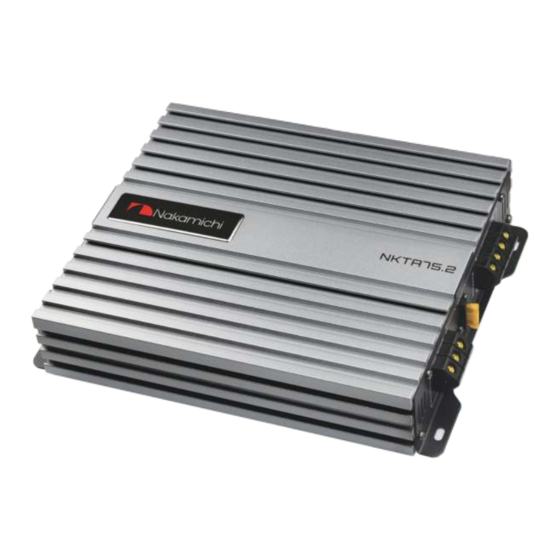
Summary of Contents for Nakamichi NKTA75.2
- Page 1 NKTA75.2 2 CHANNEL POWER AMPLIFIER nakamichicaraudio.com nakamichi.caraudio nakamichi.global...
- Page 3 Thank you for your purchase of our Nakamichi product and we warmly welcome you to the Nakamichi family! Do keep your original invoice and purchase receipt in a safe place in case of future service and warranty claims. You may also contact your appointed Nakamichi service agent for any future technical support requirements.
-
Page 4: Dimensions (Unit:mm)
DIMENSIONS (UNIT:MM) 2 EN... -
Page 5: Power Connection Leads
POWER CONNECTION LEADS BATTERY Notes on the power supply Connect the +12V power input lead only after all other leads have been connected. Be sure to connect the ground wire of the unit securely to a meatal part of the car. A lose connection may cause a malfunction of the amplifier. - Page 6 POWER CONNECTION LEADS Use the power supply lead with a fuse attached whose value is the same as original fuse. Place the fuse in power supply lead as close as possible to the car battery. During a full power operation, MaxImum current will run through the system. Therefore. Make sure the that the leads to be connected to the +12V and GND terminals of the unit respectively must be larger than 8-Gauge(AWG.8).
- Page 7 POWER CONNECTION LEADS CONNECTION 2: BRIDGE MODE 4 - 8 SPEAKER 5 EN...
-
Page 8: Panel Controls And Features
PANEL CONTROLS AND FEATURES A. HIGH LEVEL (speaker level) INPUTS If your head unit does not have RCA ouputs you can use the speaker outputs for the audio source for the subwoofer. Use the supplied cable and wire harness and connect the outputs properly as shown in the connection diagram in this manual. - Page 9 PANEL CONTROLS AND FEATURES E. SPEAKER LOW PASS CROSSOVER FREQUENCY Controls low frequency of the amplifier between 40Hz to 150Hz.. F. BASS BOOST The BASS BOOST feature will increase the sound level in the bass frequencies G. POWER AND PROTECTION INDICATOR The protection red LED will light up and flash if there is a fault present in the amplifier.
- Page 10 INTERFERENCE All cables can create interference. The power cable and cinch / RCA audio cables are very prone to interference from other sources, while remote cables are less prone. Interference is often caused by the generator, ignition, or any other electronic parts or systems.
-
Page 11: Troubleshooting
TROUBLESHOOTING If you experience operation or performance problems with this product, compare your installation with the electrical wiring diagram on the previous pages.If problems persist, read the following troubleshooting tips which may help eliminate the problems. SYMPTOM POSSIBLE CAUSE ACTION TO TAKE Check remote turn-on voltage output at amplifier and Low or no remote turn-on input correct as needed...


Need help?
Do you have a question about the NKTA75.2 and is the answer not in the manual?
Questions and answers