Table of Contents
Advertisement
Advertisement
Table of Contents

Summary of Contents for Nakamichi NGXA80.6
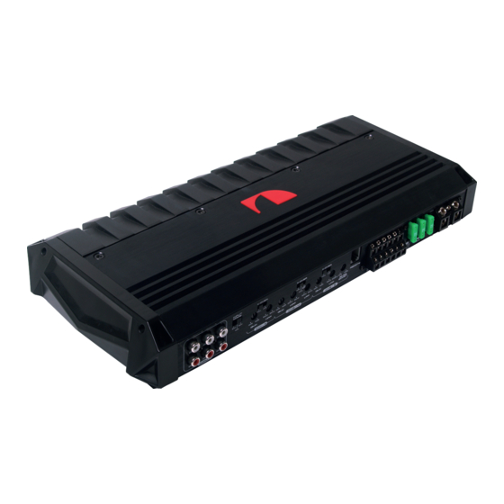
- Page 1 NGXA80.6 6-Channel Bridgeable Power Amplifier User Manual www.nakamichic-...
-
Page 2: Table Of Contents
CONTENTS INTRODUCTION 2 EN ACCESSORY LIST 2 EN SPECIFICATIONS 2 EN DIMENSIONS 3 EN PANEL CONTROLS AND FEATURES 4 EN WIRING DIAGRAM 5 EN PRECAUTIONS 6 EN FUSE REPLACEMENT 6 EN PROTECTION CIRCUIT 6 EN WIRING INSTRUCTIONS 7 EN Power Connection Ground Connection Remote Turn-On Connection Speaker Connections... -
Page 3: Accessory List
Thank you for your purchase, and welcome to Nakamichi! In order to enjoy the better service from us, please keep your original invoice well and complete. You’d better post the copy of back to the appointed service agent of Nakamichi so that you may get more technical support. - Page 4 DIMENSIONS(Unit: mm) 3 EN...
-
Page 5: Panel Controls And Features
PANEL CONTROLS AND FEATURES A. HIGH PASS CROSS FREQUENCY Controls the frequency of the power amplifier of high frequency reduction to common denominat or is 20Hz to 3KHz. B. X-OVER CONTROL Depending on the selected switch setting the amplifier operates in fullrange, highpass or Lowpass mode. C. -
Page 6: Wiring Diagram
WIRING DIAGRAM 6 CHANNEL STEREO CH2 SPEAKER 2~4 Ohm CH1 SPEAKER CH5 SPEAKER 2~4 Ohm 2~4 Ohm CH3 SPEAKER 2~4 Ohm CH6 SPEAKER 2~4 Ohm CH4 SPEAKER 2~4 Ohm REMOTE TURN ON Terminal of head unit CAR STEREO 4.1 CHANNEL CH2 SPEAKER 2~4 Ohm CH5&CH6 SPEAKER... -
Page 7: Precautions
PRECAUTIONS ● This unit is designed for negative ground 12 Volts DC operation only. ● Use speakers with an impedance of 2Ω or 4Ω (4Ω to 8Ω when used as bridged amplifier) ● Avoid installing the unit where: – It would be subject to high temperatures, such as from direct sunlight or hot air from the heater. -
Page 8: Wiring Instructions
WIRING INSTRUCTIONS POWER CONNECTION The battery terminal (BATT) must be connected directly to the positive terminal of the vehicle battery to provide an adequate voltage source and minimize noise. Connecting the battery terminal lead to any other point (such as the fuse block) will reduce the power output and may cause noise and distortion. -
Page 9: Power Connection Leads
POWER CONNECTION LEADS POWER BATTERY HEAD UNIT DC 12V To a metal part of car NOTES ON THE POWER SUPPLY: ● Connect the +12V power input lead only after all other leads have been connected. ● Be sure to connect the ground wire of the unit securely to a metal part of the car. ●... -
Page 10: Operation
OPERATION GAIN = INPUT LEVEL CONTROL ● The input level control allows the system to work well within a wide range of output level. Choose the adjustment in the way that you achieve a sound most possibly without any distortion. As a guideline the following procedure is recommended: –If you use several amplifiers, the adjustment has to be made for each set separately. -
Page 11: How To Proceed In Case Of Faults
HOW TO PROCEED IN CASE OF FAULTS No Function: ● The connection cable is not connected correctly (=terminal +12V/GND/REM). Ensure that all connections and mechanic contact and that the jacket has been removed. The fuse is defective-pay attention to the correct value of a new fuse! No Sound : ●... - Page 12 www.nakamichicaraudio.com...


Need help?
Do you have a question about the NGXA80.6 and is the answer not in the manual?
Questions and answers