Advertisement

If you have any further questions regarding your new computer, please do not hesitate to contact us either through the online customer service site
https://us.msi.com/support or by contacting our customer support at 1-626-271-1004, Monday to Friday from 9:00 a.m. to 6:00 p.m. Pacific Standard Time. You can
also contact technical support by calling 1-888-447-6564, Monday to Friday open 24 hours (Weekend and Public Holiday closed). We will reply to you as soon as possible.
Step 1
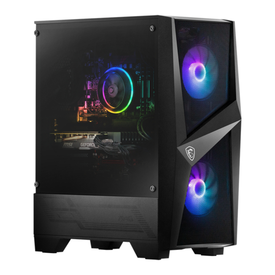
REMOVE THE TEMPERED GLASS SIDE PANEL
Remove the four thumbscrews on the tempered glass side panel. And gently
remove the tempered glass panel away from the case and place it in a safe area.
Step 3
INSPECT YOUR PC
Make sure all components and cables are seated firmly. Now, you can replace
the tempered glass side panel and secure with thumbscrews.
Step 5
CONNECT WIFI ANTENNAE, KEYBOARD & MOUSE
Screw the Wi-Fi Antennae to the gold contact points on the rear of the case.
Plug the mouse and the keyboard into any of the USB ports.
IMPORTANT
PLEASE READ BEFORE TURNING ON THE DESKTOP
Step 2
Carefully pull the foam packaging out the system. It should come out easily
without having to apply any force.
Step 4
Connect your monitor to either display ports or HDMI ports on the graphics
cards.
Step 6
Plug the power cable into the power cable socket and plug the other end of
the power cable into a power outlet. Turn the power supply switch on by
having the "I" symbol on the switch pressed down. Press the power button.
REMOVE THE FOAM PACKAGING
Know Your Video Connectors
CONNECT YOUR MONITOR
POWER ON YOUR DESKTOP
Scan for setup
video guides
USB Type-C
Mini DisplayPort
DVI
HDMI
DisplayPort
G52-B0Y22X1-LAX

Advertisement

Table of Contents
loading
Need help?

Need help?

Do you have a question about the Codex R 12th and is the answer not in the manual?

Questions and answers

Summary of Contents for MSI Codex R 12th

  • Page 1 If you have any further questions regarding your new computer, please do not hesitate to contact us either through the online customer service site https://us.msi.com/support or by contacting our customer support at 1-626-271-1004, Monday to Friday from 9:00 a.m. to 6:00 p.m. Pacific Standard Time. You can also contact technical support by calling 1-888-447-6564, Monday to Friday open 24 hours (Weekend and Public Holiday closed).
  • Page 2: Table Of Contents

    JCOM1: Serial Port Connector .................22 JRGB1: RGB LED connector ..................22 JRAINBOW1~2: Addressable RGB LED connectors ..........23 EZ Debug LED ......................23 Installing OS, Drivers & MSI Center .............. 24 Installing Windows 10/ Windows 11 .................24 Installing Drivers ......................24 MSI Center ........................24...
  • Page 3 UEFI BIOS ....................... 25 BIOS Setup ........................26 Entering BIOS Setup ....................26 BIOS User Guide .......................26 Resetting BIOS ......................27 Updating BIOS......................27 Contents...
  • Page 4: Safety Information

    Safety Information ∙ The components included in this package are prone to damage from electrostatic discharge (ESD). Please adhere to the following instructions to ensure successful computer assembly. ∙ Ensure that all components are securely connected. Loose connections may cause the computer to not recognize a component or fail to start.
  • Page 5: Specifications

    Specifications ∙ Supports 12th Gen Intel® Core™ Processors ∙ Processor socket LGA1700 * Please go to www.msi.com to get the newest support status as new processors are released. Chipset Intel® B660 chipset ∙ 4x DDR5 memory slots, support up to 128GB* ∙...
  • Page 6 Continued from previous page Intel® Wi-Fi 6 ∙ The Wireless module is pre-installed in the M.2 (Key-E) slot Wireless LAN & ∙ Supports MU-MIMO TX/RX, 2.4GHz/ 5GHz (160MHz) Bluetooth® up to 2.4Gbps ∙ Supports 802.11 a/ b/ g/ n/ ac/ ax ∙...
  • Page 7 Continued from previous page ∙ 1x 24-pin ATX main power connector ∙ 1x 8-pin ATX 12V power connector ∙ 1x 4-pin ATX 12V power connector ∙ 6x SATA 6Gb/s connectors ∙ 2x M.2 slots (M-Key) ∙ 1x USB 3.2 Gen 1 5Gbps Type-C port 1x USB 3.2 Gen 1 5Gbps connectors (supports ∙...
  • Page 8 ACPI 6.4, SMBIOS 3.4 ∙ Multi-language ∙ Drivers ∙ MSI Center ∙ Intel® Extreme Tuning Utility Software ∙ CPU-Z MSI GAMING ∙ Google Chrome™, Google Toolbar, Google Drive ∙ Norton™ Internet Security Solution ∙ LAN Manager ∙ Mystic Light ∙ Ambient Devices ∙...
  • Page 9 Continued from previous page ∙ Audio ▪ Audio Boost ∙ Network ▪ 2.5G LAN ▪ LAN Manager ▪ Intel WiFi ∙ Cooling ▪ M.2 Shield Frozr Special Features ▪ 7W/mK MOSFET thermal pad ▪ Pump Fan ▪ Smart Fan Control ∙...
  • Page 10 Dual CPU Power ▪ 2oz Copper thickened PCB Special Features ∙ Protection ▪ PCI-E Steel Armor ∙ Experience ▪ MSI Center ▪ Click BIOS 5 ▪ EZ M.2 Clip ▪ Forzr AI Cooling ▪ CPU Cooler Tuning ▪ EZ DEBUG LED App Player ▪...
  • Page 11: Rear I/O Panel

    Rear I/O Panel Line-out PS/2 Combo port Line-in Wi-Fi Antenna 2.5 Gbps LAN connectors USB 3.2 Gen 1 5Gbps Type-A USB 3.2 Gen 2 USB 2.0 Type-A Mic-in 10Gbps Type-A USB 3.2 Gen 2 10Gbps Type-C LAN Port LED Status Table Link/ Activity LED Speed LED Status...
  • Page 12: Overview Of Components

    Overview of Components DIMMA1 Processor Socket DIMMA2 CPU_PWR2 CPU_FAN1 DIMMB1 CPU_PWR1 DIMMB2 JRAINBOW1 PUMP_FAN1 SYS_FAN1 ATX_PWR1 52mm* M2_1 JUSB3 SYS_FAN2 JUSB4 PCI_E1 SATA▼5▲6 PCI_E2 SATA▼7▲8 PCI_E3 M2_2 PCI_E4 JCI1 JFP2 JAUD1 JRGB1 SATA_A JDASH1 SATA_B JRAINBOW2 JFP1 JUSB1 JTPM1 JUSB2 JCOM1 JBAT1 JLPT1...
  • Page 13: Cpu Socket

    Always unplug the power cord from the power outlet before installing or removing ∙ the CPU. ∙ Please retain the CPU protective cap after installing the processor. MSI will deal with Return Merchandise Authorization (RMA) requests if only the motherboard comes with the protective cap on the CPU socket. ∙...
  • Page 14: Dimm Slots

    DIMM Slots Please install the memory module into the DIMM slot as shown below. Memory module installation recommendation DIMMA2 DIMMA2 DIMMB2 DIMMA1 DIMMA2 DIMMB1 DIMMB2 Overview of Components...
  • Page 15: Pci_E1~4: Pcie Expansion Slots

    If you install a large and heavy graphics card, you need to use a tool such as MSI ∙ Gaming Series Graphics Card Bolster to support its weight to prevent deformation of the slot.
  • Page 16: Jfp1, Jfp2: Front Panel Connectors

    JFP1, JFP2: Front Panel Connectors These connectors connect to the switches and LEDs on the front panel. HDD LED + Power LED + Power LED Power Switch HDD LED - Power LED - Reset Switch Power Switch Reserved Reset Switch Power Switch HDD LED Reset Switch...
  • Page 17: Sata5~8, Sata_A1& Sata_B1: Sata 6Gb/S Connectors

    SATA5~8, SATA_A1& SATA_B1: SATA 6Gb/s Connectors These connectors are SATA 6Gb/s interface ports. Each connector can connect to one SATA device. SATA6 SATA5 SATA8 SATA7 SATA_B1 SATA_A1 ⚠ Important SATA7 will be unavailable when installing M.2 SATA SSD in the M2_2 slot. ∙...
  • Page 18: Atx_Pwr1, Cpu_Pwr1~2: Power Connectors

    ATX_PWR1, CPU_PWR1~2: Power Connectors These connectors allow you to connect an ATX power supply. +3.3V +3.3V +3.3V -12V Ground Ground PS-ON# Ground Ground Ground ATX_PWR1 Ground Ground PWR OK 5VSB +12V +12V +3.3V Ground Ground +12V Ground +12V CPU_PWR1 Ground +12V Ground +12V...
  • Page 19: Jusb1~2: Usb 2.0 Connectors

    In order to recharge your iPad,iPhone and iPod through USB ports, please install ∙ MSI Center utility. JUSB3: USB 3.2 Gen 1 Connector This connector allows you to connect USB 3.2 Gen 1 5Gbps ports on the front panel.
  • Page 20: Jusb4: Usb 3.2 Gen 1 Type-C Connector

    JUSB4: USB 3.2 Gen 1 Type-C Connector This connector allows you to connect USB 3.2 Gen 1 Type-C connector on the front panel. The connector possesses a foolproof design. When you connect the cable, be sure to connect it with the corresponding orientation. JUSB4 USB Type-C Cable USB Type-C port on the...
  • Page 21: Cpu_Fan1, Pump_Fan1, Sys_Fan1~2: Fan Connectors

    CPU_FAN1, PUMP_FAN1, SYS_FAN1~2: Fan Connectors Fan connectors can be classified as PWM (Pulse Width Modulation) Mode or DC Mode. PWM Mode fan connectors provide constant 12V output and adjust fan speed with speed control signal. DC Mode fan connectors control fan speed by changing voltage.
  • Page 22: Jci1: Chassis Intrusion Connector

    JCI1: Chassis Intrusion Connector This connector allows you to connect the chassis intrusion switch cable. Normal Trigger the chassis (default) intrusion event Using chassis intrusion detector Connect the JCI1 connector to the chassis intrusion switch/ sensor on the chassis. Close the chassis cover. Go to BIOS >...
  • Page 23: Jbat1: Clear Cmos (Reset Bios) Jumper

    (12V/G/R/B) with the maximum power rating of 3A (12V). ∙ Always turn off the power supply and unplug the power cord from the power outlet before installing or removing the RGB LED strip. Please use MSI’s software to control the extended LED strip. ∙ Overview of Components...
  • Page 24: Jrainbow1~2: Addressable Rgb Led Connectors

    ∙ before installing or removing the RGB LED strip. ∙ Please use MSI’s software to control the extended LED strip. EZ Debug LED These LEDs indicate the status of the motherboard. CPU - indicates CPU is not detected or fail.
  • Page 25: Installing Os, Drivers & Msi Center

    MSI Center is an application that helps you easily optimize game settings and smoothly use content creation softwares. It also allows you to control and synchronize LED light effects on PCs and other MSI products. With MSI Center, you can customize ideal modes, monitor system performance, and adjust fan speed.
  • Page 26: Uefi Bios

    UEFI has many new functions and advantages that traditional BIOS cannot achieve, and it will completely replace BIOS in the future. The MSI UEFI BIOS uses UEFI as the default boot mode to take full advantage of the new chipset’s capabilities.
  • Page 27: Bios Setup

    * When you press F10, a confirmation window appears and it provides the modification information. Select between Yes or No to confirm your choice. BIOS User Guide If you’d like to know more instructions on setting up the BIOS, please refer to http://download.msi.com/manual/mb/Intel600BIOS.pdf or scan the QR code to access. UEFI BIOS...
  • Page 28: Resetting Bios

    Updating BIOS Updating BIOS with M-FLASH Before updating: Please download the latest BIOS file that matches your motherboard model from MSI website. And then save the BIOS file into the USB flash drive. Updating BIOS: Insert the USB flash drive that contains the update file into the USB port.
  • Page 29 Please close all other application software before updating the BIOS. ∙ To update BIOS: Install and launch MSI Center and go to Support page. Select Live Update and click on Advance button. Select the BIOS file and click on Install button.
  • Page 30 Case Features / 機殼特色 Optimized Air Flow RGB Fan Included Tool-Less Tempered Glass Magnetic Filter 最佳風流設計 內含RGB風扇 無螺絲與強化玻璃側板 磁吸防塵網 For MAG FORGE 100R only 僅 MAG FORGE 100R 支援 ARGB Fan Included Mystic Light 1 to 6 ARGB Control Board 內含ARGB風扇...
  • Page 31 Accessories / 配件 Specification / 產品規格 Item 項目 Name 名稱 / Q’ty 數量 Used for 用途 MAG FORGE 100M MAG FORGE 101M MAG FORGE 100R 1 to 6 RGB (4pin) 1 to 6 RGB (4pin) 1 to 6 ARGB (3pin) Fan LED Controller Cable ties Control Board...

This manual is also suitable for:

12tc-059us

Table of Contents

Save PDF