Aruba AP-105 - Wireless Access Point Installation Manual
- Installation manual (2 pages) ,
- Installation manual (2 pages)
Advertisement
- 1 About the Aruba AP-105 Access Points
- 2 Package Contents
- 3 AP-105 Hardware Overview
- 4 Before You Begin
- 5 Verifying Pre-Installation Connectivity
- 6 Identifying Specific Installation Locations
- 7 Installing the AP
- 8 Verifying Post-Installation Connectivity
- 9 Configuring the AP-105
- 10 Product Specifications
- 11 Contacting Aruba Networks
- 12 Documents / Resources
About the Aruba AP-105 Access Points
The Aruba AP-105 wireless access point supports the IEEE 802.11n standard for high-performance WLAN. This access point uses MIMO (Multiple-in, Multipleout) technology and other high-throughput mode techniques to deliver highperformance, 802.11n 2.4 GHz and 5 GHz functionality while simultaneously supporting existing 802.11a/b/g wireless services. The AP-105 access point works only in conjunction with an Aruba Controller.
The Aruba AP-105 access point provides the following capabilities:
- Wireless transceiver
- Protocol-independent networking functionality
- IEEE 802.11a/b/g/n operation as a wireless access point
- IEEE 802.11a/b/g/n operation as a wireless air monitor
- Compatibility with IEEE 802.3af PoE
- Central management configuration and upgrades through an Aruba Controller
Package Contents
- AP-105 access point (1 unit or a pack of 10)
- Installation guide (this document)
 Inform your supplier if there are any incorrect, missing, or damaged parts. If possible, retain the carton, including the original packing materials. Use these materials to repack and return the unit to the supplier if nee

AP-105 Hardware Overview

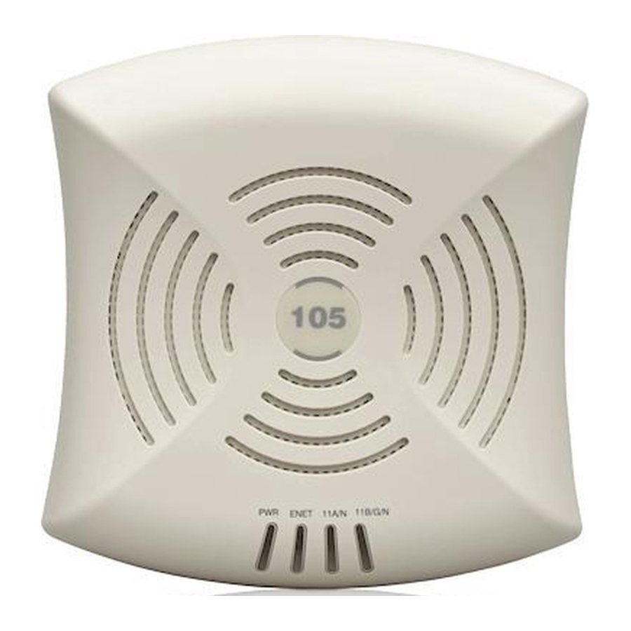
LEDs
The AP-105 is equipped with four LEDs that indicate the status of the various components of the AP.
- PWR: Indicates whether or not the AP-105 is powered-on
- ENET: Indicates the status of the AP-105's Ethernet port
- 11A/N: Indicates the status of the 802.11a/n radio
- 11B/G/N: Indicates the status of the 802.11b/g/n radio
For information about the AP-105's LED behavior, see Table 1.

Console Port
Use the console port to connect to a terminal for direct local management.
Ethernet Port
AP-105 is equipped with a single 10/100/1000Base-T (RJ-45) auto-sensing, MDI/ MDX wired-network connectivity port. This port supports IEEE 802.3af Power over Ethernet (PoE) compliance, accepting 48VDC as a standard defined Powered Device (PD) from a Power Sourcing Equipment (PSE) such as a PoE midspan injector, or network infrastructure that supports PoE.
DC Power Socket
If PoE is not available, an optional Aruba AP AC-DC adapter kit (sold separately) can be used to power the AP-105.
Before You Begin

FCC Statement: Improper termination of access points installed in the United States configured to non-US model controllers will be in violation of the FCC grant of equipment authorization. Any such willful or intentional violation may result in a requirement by the FCC for immediate termination of operation and may be subject to forfeiture (47 CFR 1.80).
EU Statement:
Lower power radio LAN product operating in 2.4 GHz and 5 GHz bands. Please refer to the ArubaOS User Guide for details on restrictions.
Pre-Installation Network Requirements
After WLAN planning is complete and the appropriate products and their placement have been determined, the Aruba controller(s) must be installed and initial setup performed before the Aruba APs are deployed.
For initial setup of the controller, refer to the ArubaOS Quick Start Guide for the software version installed on your controller.
AP Pre-Installation Checklist
Before installing your AP-105 access point, be sure that you have the following:
- CAT5 UTP cable of required length
- One of the following power sources:
- IEEE 802.3af-compliant Power over Ethernet (PoE) source
- Supports full functionality for AP-105
- The POE source can be any power source equipment (PSE) controller or midspan PSE device
- Aruba AP AC-DC adapter kit (sold separately)
- Aruba Controller provisioned on the network: „
- Layer 2/3 network connectivity to your access point „
- One of the following network services:
- Aruba Discovery Protocol (ADP)
- DNS server with an "A" record
- DHCP Server with vendor-specific options
Summary of the Setup Process
It is important that you verify the items listed under AP Pre-Installation Checklist before you attempt to set up and install an AP-105.
Successful setup of an AP-105 access point consists of five tasks, which must be performed in this order:
- Verify pre-installation connectivity.
- Identify the specific installation location for each AP.
- Install each AP.
- Verify post-installation connectivity.
- Configure each AP.
Aruba Networks, Inc., in compliance with governmental requirements, has designed the AP-105 access points so that only authorized network administrators can change the settings. For more information about AP configuration, refer to the ArubaOS Quick Start Guide and ArubaOS User Guide.
Access points are radio transmission devices and as such are subject to governmental regulation. Network administrators responsible for the configuration and operation of access points must comply with local broadcast regulations. Specifically, access points must use channel assignments appropriate to the location in which the access point will be used.
Verifying Pre-Installation Connectivity
Before you install APs in a network environment, make sure that the APs are able to locate and connect to the controller after power on.
Specifically, you must verify the following conditions:
- When connected to the network, each AP is assigned a valid IP address
- APs are able to locate the controller
Refer to the ArubaOS Quick Start Guide for instructions on locating and connecting to the controller.
Identifying Specific Installation Locations
RF Radiation Exposure Statement: This equipment complies with FCC RF radiation exposure limits. This equipment should be installed and operated with a minimum distance of 13.78 inches (35 cm) between the radiator and your body for 2.4 GHz and 5 GHz operations. This transmitter must not be co-located or operating in conjunction with any other antenna or transmitter. When operated in the 5.15 to 5.25 GHz frequency range, this device is restricted to indoor use to reduce the potential for harmful interference with co-channel Mobile Satellite Systems.
You can mount the AP-105 access point on a wall or on the ceiling. Use the AP placement map generated by Aruba's RF Plan software application to determine the proper installation location(s). Each location should be as close as possible to the center of the intended coverage area and should be free from obstructions or obvious sources of interference. These RF absorbers/reflectors/interference sources will impact RF propagation and should have been accounted for during the planning phase and adjusted for in RF plan.
Identifying Known RF Absorbers/Reflectors/Interference Sources
Identifying known RF absorbers, reflectors, and interference sources while in the field during the installation phase is critical. Make sure that these sources are taken into consideration when you attach an AP to its fixed location.
RF absorbers include:
- Cement/concrete—Old concrete has high levels of water dissipation, which dries out the concrete, allowing for potential RF propagation. New concrete has high levels of water concentration within the concrete, blocking RF signals.
- Natural Items—Fish tanks, water fountains, ponds, and trees
- Brick
RF reflectors include:
- Metal Objects—Metal pans between floors, rebar, fire doors, air conditioning/ heating ducts, mesh windows, blinds, chain link fences (depending on aperture size), refrigerators, racks, shelves, and filing cabinets
- Do not place an AP between two air conditioning/heating ducts. Make sure that APs are placed below ducts to avoid RF disturbances.
RF interference sources include:
- Microwave ovens and other 2.4 or 5 GHz objects (such as cordless phones)
- Cordless headset such as those used in call centers or lunch rooms
Installing the AP
Service to all Aruba Networks products should be performed by trained service personnel only.
Using the Integrated Wall-Mounting Slots
The keyhole-shaped slots on the back of the AP can be used to attach the device upright to an indoor wall or shelf. When you choose the mounting location, allow additional space at the right of the unit for cables.
- Since the ports are on the back of the device, make sure that you mount the AP is such a way that there is a clear path to the Ethernet port, such as a predrilled hole in the mounting surface.
- At the mounting location, install two screw on the wall or shelf, 1 7/8 inches (4.7 cm) apart. If you are attaching the device to drywall, Aruba recommends using appropriate wall anchors (not included).
- Align the mounting slots on the rear of the AP over the screws and slide the unit into place (see Figure 4).

Using the Integrated Ceiling Tile Rail Slots
The snap-in tile rail slots on the rear of the AP can be used to securely attach the device directly to a 15/16" wide, standard ceiling tile rail.
![]() Make sure the AP fits securely on the ceiling tile rail when hanging the device from the ceiling; poor installation could cause it to fall onto people or equipment.
Make sure the AP fits securely on the ceiling tile rail when hanging the device from the ceiling; poor installation could cause it to fall onto people or equipment.
- Pull the necessary cables through a prepared hole in the ceiling tile near where the AP will be placed.
- If necessary, connect the console cable to the console port on the back of the AP.
Hold the AP next to the ceiling tile rail with the ceiling tile rail mounting slots at approximately a 30-degree angle to the ceiling tile rail (see Figure 5). Make sure that any cable slack is above the ceiling tile.

- Pushing toward the ceiling tile, rotate the AP clockwise until the device clicks into place on the ceiling tile rail.
Connecting Required Cables
Install cables in accordance with all applicable local and national regulations and practices.
Ethernet Ports
The RJ45 Ethernet port (ENET) supports 10/100/1000Base-T auto-sensing MDI/
MDX connections. Use these ports to connect the AP to a twisted pair Ethernet LAN segment or directly to an Aruba Controller. Use a 4- or 8-conductor, Category 5 UTP cable up to 100 m (325 feet) long.
The 10/100/1000 Mbps Ethernet port is on the back of the AP. The port has an RJ45 female connector with the pin-outs shown in Figure 6.
Figure 6 Gigabit Ethernet Port Pin-Out

| RJ-45 Female Pin-Out | Signal Name | Function |
| 1 | BI_DA+ | Bi-directional pair +A |
| 2 | BI_DA- | Bi-directional pair -A |
| 3 | BI_DB+ | Bi-directional pair +B |
| 4 | BI_DC+ | Bi-directional pair +C |
| 5 | BI_DC- | Bi-directional pair -C |
| 6 | BI_DB- | Bi-directional pair -B |
| 7 | BI_DD+ | Bi-directional pair +D |
| 8 | BI_DD- | Bi-directional pair -D |
Serial Console Port
The serial console port (Console) allows you to connect the AP to a serial terminal or a laptop for direct local management. This port is an RJ-45 female connector with the pinouts described in Figure 7. Connect this port in one of the following ways:
- Connect it directly to a terminal or terminal server using an Ethernet cable.
- Use a modular adapter to convert the RJ-45 (female) connector on the AP to a DB-9 (male) connector, and connect the adapter to a laptop using an RS-232 cable. See Figure 8 for connector details of the adapter.

Power Connection
The AP-105 has a single 12V DC power jack socket to support powering through an AC-to-DC power adapter.
If both POE and DC power are available, the AP uses POE even when there is not enough POE voltage available to power the AP.
Verifying Post-Installation Connectivity
The integrated LEDs on the AP can be used to verify that the AP is receiving power and initializing successfully (see Table 1). Refer to the ArubaOS Quick Start Guide for further details on verifying post-installation network connectivity.
Table 1 AP-105 Series LED Meanings
| LED | Color/State | Meaning |
| PWR | Off | No power to AP |
| Green flashing | System initializing | |
| Red steady | System failed to initialize, contact TAC | |
| Green steady | Power on, device ready | |
| ENET (10/100/1000 Mbps) | Off | No link |
| Green on | 1000 Mbps link | |
| Amber on | 10/100 Mbps link | |
| Green flashing | Ethernet link activity | |
| 11A/N | Off | 5 GHz radio is disabled |
| Amber | 5 GHz radio enabled in WLAN mode | |
| Green | 5 GHz radio enabled in 11n mode | |
| Green flashing | 5 GHz Air Monitor or RF Protect mode | |
| 11B/G/N | Off | 2.4 GHz radio disabled |
| Amber | 2.4 GHz radio enabled in WLAN mode | |
| Green | 2.4 GHz radio enabled in 11n mode | |
| Green flashing | 2.4 GHz Air Monitor or RF Protect mode |
Configuring the AP-105
AP Provisioning/Reprovisioning
Provisioning parameters are unique to each AP. These local AP parameters are initially configured on the controller which are then pushed out to the AP and stored on the AP itself. Aruba recommends that provisioning settings be configured via the ArubaOS Web UI only. Refer to the ArubaOS User Guide for complete details.
AP Configuration
Configuration parameters are network or controller specific and are configured and stored on the controller. Network configuration settings are pushed out to the AP(s) but remain stored on the controller.
Configuration settings can be configured via the ArubaOS Web UI, ArubaOS CLI, or Aruba MMS. Refer to their respective guides for further details: the ArubaOS User Guide or Aruba Mobility Management System User Guide.
Product Specifications
Mechanical
- Dimensions (antenna stowed) (HxWxD):
- 5.2 inches x 5.3 inches x 1.8 inches
- 13.2 cm x 13.5 cm x 4.5 cm
- Weight: 300g/0.66 lbs.
- Temperature:
- Operating: 0ºC to 50ºC (32ºF to 122ºF)
- Storage: –10ºC to 70ºC (14ºF to 158ºF)
- Relative Humidity: 5% to 95% non-condensing
- Altitude: 8,000 ft @ 28ºC (82.4ºF)
- Mounting: Wall, ceiling, or desktop mountable
- Antennas: Integrated
- Visual Status Indicators (LEDs): See Table 1
Electrical
- Ethernet:
- „ 1 x 10/100/1000Base-T auto-sensing Ethernet RJ-45 Interfaces
- „ MDI/MDX
- „ IEEE 802.3 (10Base-T), IEEE 802.3u (100Base-T). IEEE 802.3ab (1000Base-T)
- „ Power over Ethernet (IEEE 802.3af compliant), 48V DC/350mA (see Table 1 for pin configuration)
- Power:
- 12 VDC power interface, supports powering through an AC-to-DC power adapter
If a power adapter other than the one provided by Aruba Networks is used in the US or Canada, it should be cULus (NRTL) Listed, with an output rated 12 VDC, minimum 1.25A, marked "LPS" or "Class 2," and suitable for plugging into a standard power receptacle in the US and Canada.
Wireless LAN
- Network Standards: IEEE 802.11b, IEEE 802.11g, IEEE 802.11a, and IEEE 802.11n (draft)
- Antenna Type:
- Internal
- 2x 802.11a/n
- 2x 802.11b/g/n
- Internal
- Antenna Gain (Integrated Antennas):
- 2.4 – 2.5 GHz/2.5 dBi (max)
- 5.180 – 5.825 GHz/4.0 dBi (max)
- Radio Technology:
- Orthogonal Frequency Division Multiplexing (OFDM)
- Direct Sequence Spread Spectrum (DSSS)
- Radio Modulation Type:
- „ 802.11b - CCK, BPSK, QPSK
- „ 802.11g - CCK, BPSK, QPSK,16-QAM, 64-QAM
- „ 802.11a - BPSK, QPSK,16-QAM, 64-QAM
- „ 802.11n draft 2.0
- Media Access Control: CSMA/CA with ACK
- Supported Frequency Bands 2.4GHz:
- 2.400 ~ 2.4835GHz (Global), channels country specific
- Supported Frequency Bands 5GHz:
- „ 5.150 ~ 5.250GHz (low band), country-specific
- „ 5.250 ~ 5.350GHz (mid band), country-specific
- „ 5.470 ~ 5.725GHz (Europe), country-specific
- „ 5.725 ~ 5.825GHz GHz (high band), country-specific
- Data Rates:
- „ 802.11b - 1, 2, 5.5, 11 Mbps per channel
- „ 802.11g - 6, 9, 12, 18, 24, 36, 48 and 54 Mbps per channel
- „ 802.11a - 6, 9, 12, 18, 24, 36, 48 and 54 Mbps per channel
- „ 802.11n - Data rate MCS0 – MCS15 (from 6.5 Mbps to 300 Mbps)
Contacting Aruba Networks
Table 1
| Web Site Support | |
| Main Site | http://www.arubanetworks.com; |
| Support Site | https://support.arubanetworks.com ; |
| Software Licensing Site | https://licensing.arubanetworks.com/login.php |
| Wireless Security Incident Response Team (WSIRT) | http://www.arubanetworks.com/support/wsirt.php |
| Americas and APAC Support Email | support@arubanetworks.com |
| EMEA Support Email | emea.support@arubanetworks.com |
| WSIRT Email Please email details of any security problem found in an Aruba product. | wsirt@arubanetworks.com |
Table 2
| Telephone Support | |
| Aruba Corporate | +1 (408) 227-4500 |
| FAX | +1 (408) 227-4550 |
www.arubanetworks.com
1344 Crossman Avenue
Sunnyvale, California 94089
Phone: 408.227.4500
Fax 408.227.4550

Documents / Resources
References
Download manual
Here you can download full pdf version of manual, it may contain additional safety instructions, warranty information, FCC rules, etc.
Download Aruba AP-105 - Wireless Access Point Installation Manual
Advertisement


Need help?
Do you have a question about the AP-105 and is the answer not in the manual?
Questions and answers