Yaesu FP-1030A - Regulated DC Power Supply Operating Manual
- Operating instructions (2 pages)
Advertisement
INTRODUCTION
The Yaesu FP-1030A is a high-quality, Regulated DC Power Supply specifically designed for use with DC powered radio equipment. The FP-1030A provides 13.8 Volts DC at up to 25 Amps (continuous duty).
Please read these operating instructions thoroughly so as to ensure proper installation and utilization of this unit. We recommend that these instructions be kept permanently for your future reference.
Features
Overload Protection
A current fold back circuit is utilized to prevent damage to the unit from excessive current drain. An "Overload" indicator becomes illuminated when am overload condition exists.
Note: Should the overload protection circuitry be activated, switch off the power supply and disconnect the external equipment immediately.
Extended operation under overload conditions may eventually cause damage the power supply.
High RFI Immunity
The FP-1030A is specifically designed for use with radio communication equipment.
It therefore includes extensive filtering to provide high immunity from erratic operation which might be caused by Radio Frequency interference (RFI).
Multiple DC Output connections
Besides the two pairs of (6A) snap-in DC connections and the (25A) screw-on DC output terminal, the FP-1030A features a cigar-lighter type DC output jack for radio equipment equipped with a hatching cigar-lighter plug.
Note: Do not attempt to use a cigar lighter in this DC output port, as it is not designed for this application, and damage the power supply may result.
Installation Tips
Like any electronic apparatus, the FP-1030A should be installed in a location which allows free air circulation, so as to provide efficient cooling for the power supply circuitry. The FP-1030A should not be installed in locations exposed to moisture, as a significant electric shock hazard will exist.
We recommend that this unit not be installed in extremely hot, dusty, or humid locations, nor in areas expcosed to direct sunshine.
Connections and Operation
- Confirm that the AC voltage as indicated on the rear panel label matches the AC mains voltage in your area.
- Connect a good earth ground to the GND terminal on the bottom case, using a heavy, braided cable for connection to your main station ground system.
- Be sure the FP-1030A is turned OFF, then plug the AC cable into your station's wall outlet.
- Confirm the expected current drain for the radio(s) to be connected to the FP-1030A. The two pairs of snap-in terminals can only handle a combined current of 6 Amps, while the screw-on terminal can provide up to 25 Amps.
- Connect each radio's Negative (usually Black) DC cable to the appropriate Black (–) terminal on the FP-1030A, and connect each radio's Positive (usually Red) DC cable to the appropriate Red (+) terminal.
- Tum the FP-1030A ON first, then tum on the radio(s) connected to the power supply. Operation may now commence.
- When operation is completed, turn the radio (s) OFF first, then tum off the power supply.

- Do not Exceed the total current rating for this power supply. This unit is designed to provide a maximum aggregate current of 25 Amps (total of all output terminals). Also, do not exceed a total current; drain of 6 Amps (combined) from the two pairs of snap-in output terminals.
- Do not use this power supply for any purpose other than powering radio communication equipment. It is not designed for other purposes such as battery charging, cigarette lighting, powering of motorized equipment, nor for lamps (other than the incidental lamps inside radio equipment).
- If the AC input fuse should blow, determine the cause of the failure before replacing the fuse. When replacing fuses, use only the specified size for the AC voltage in use.
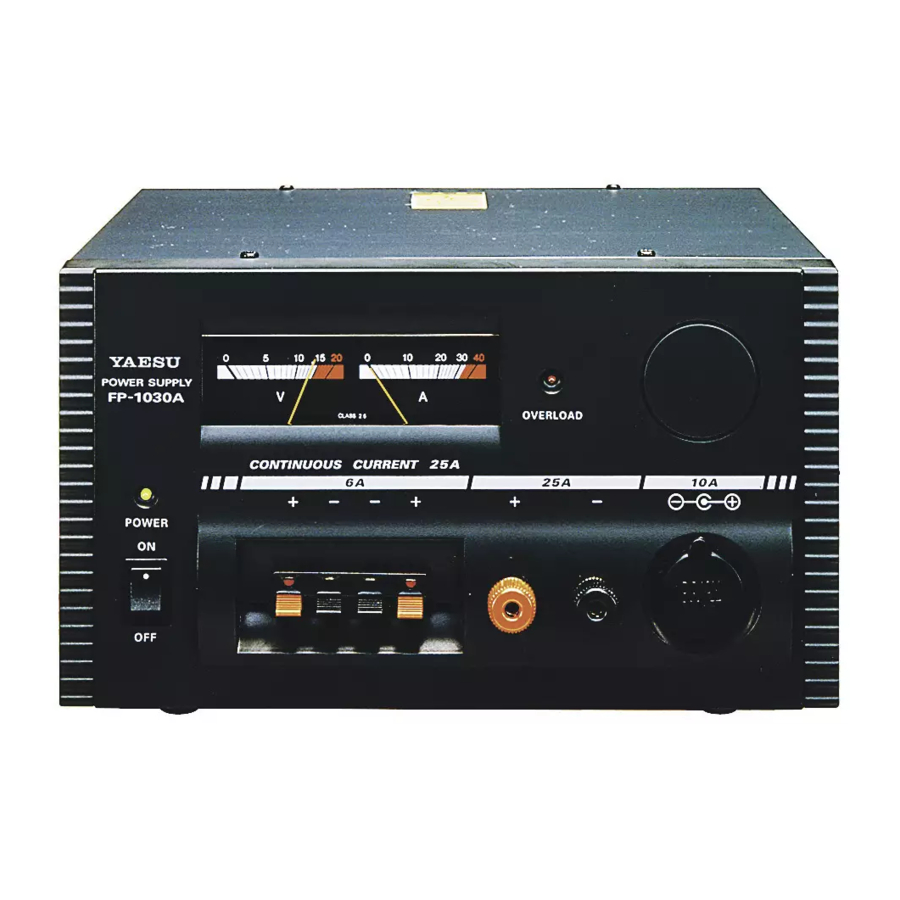
Panel Components

- POWER SWITCH
When the FP-1030A is turned on, the indicator above the Power switch lights up. - METER
Both Current ( " A " ) and Output Voltage ( " V " ) may be monitored simultaneously. - OVERLOAD INDICATOR
This indicator lights up when the Overload Protection circuitry is activated due to improper operating conditions. - GND TERMINAL
This terminal is located on the bottom case, and should be connected to a good earth ground using a heavy, braided cable (not supplied). - OUTPUT TERMINAL (25A)
This is the high-capacity (25A) output terminal.
The Red terminal is positive (+), and the Black terminal is negative (-) - DC POWER SOCKET (10A)
This is a cigar-lighter type socket, capable of supplying up to 10 Amps of current (negative ground only). - OUTPUT TERMINALS (6A)
These two pairs of snap-in output terminals can provide up to 6 Amps maximum current (combined).
The Red terminals are positive (+) and the Black terminals are negative (-).
Specifications
| VOLTAGE TYPE | AC 120V | AC 230V | AC 240V |
| RATED VOLTAGE RANGE | ±7% | ||
| OUTPUT VOLTAGE | 13.8V DC (FIXED) | ||
| OUTPUT CURRENT | 25 A CONTINUOUS | ||
| OVERLOAD PROTECTION | 27 A | ||
| RIPPLE VOLTAGE | BETTER THAN 3mVp-p AT 13.8V, 25 A | ||
| COOLING SYSTEM | THERMOSTATICALLY-CONTROLLED COOLING FAN | ||
| CIRCUIT TYPE | LINEAR SERIES | ||
| AC INPUT FUSE | 8 A | 5 A | |
| WEIGHT | 9.5 kg (20.9 LBS) | ||
| DIMENSIONS | 230 (W) x 150 (H) x 240 (D) (9.8" x 5.9" x 9.5") | ||
Safety Precautions
The following common-sense precautions must be observed to help prevent possibly-fatal electric shock.
- NEVER remove the metal cover of the power supply while AC power is connected.
- NEVER touch the power supply when your hands are wet.
- NEVER operate the power supply if foreign materials such as metallic objects, water, or other debris have fallen inside. Contact your Yaesu Dealer for assistance regarding inspection and/or repair of your unit.
- Never operate a unit which has been damaged, as the voltage regulation circuitry may have been disabled. The resulting high DC voltage could cause damage to your radio equipment.
- Never allow foreign objects to touch the DC Power Output terminals.
- If you have the need to inspect the interior of the power supply, be certain to let it cool off completely, as some components may be hot enough to burn your hands in the event of component failure.
VERTEX STANDARD CO., LTD.
4-8-8 Nakameguro, Meguro-Ku, Tokyo 153-8644, Japan
VERTEX STANDARD
US Headquarters
17210 Edwards Rd., Cerritos, CA 90703, U.S.A.
International Division
8350 N.W. 52nd Terrace, Suite 201, Miami, FL 33166, U.S.A.
YAESU EUROPE B.V.
P.O. Box 75525, 1118 ZN Schiphol. The Netherlands
YAESU UK LTD.
Unit 12, Sun Valley Business Park, Winnall Close
Winchester, Hampshire, SO23 0LB, U.K.
YAESU GERMANY GmbH
Am Kronberger Hang 2, D-65824 Schwalbach, Germany
Documents / ResourcesDownload manual
Here you can download full pdf version of manual, it may contain additional safety instructions, warranty information, FCC rules, etc.
Download Yaesu FP-1030A - Regulated DC Power Supply Operating Manual
Advertisement


Need help?
Do you have a question about the FP-1030A and is the answer not in the manual?
Questions and answers