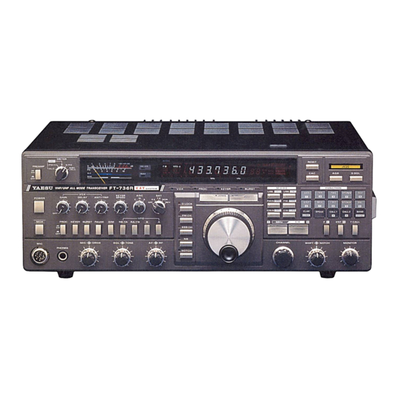
Yaesu FT-736R Repair Manual
Hide thumbs
Also See for FT-736R:
- Technical supplement (199 pages) ,
- Operating manual (67 pages) ,
- Operating manual (66 pages)
Advertisement
Quick Links
The built in AC/DC power supply on the FT-736R commonly fails after about 10 years of
normal use. The reason is usually faulty electrolytic capacitors (dried out) or bad solder joints
on the switch mode power supply board FP-1274A.
The first symptoms of the failing internal power supply are that it fails to start properly and only
a few LEDs on front panel are dimly lit. If the power supply doesn't fail outright, the problem
ultimately leads to a rig that will not power up at all with the internal power supply. The most
likely sources of this problem are C9 (a 220uF/35 V capacitor with a defective ESR of 450 ohms
or more!), and C12 1uF/50V (with a defective ESR of 60 ohms or more). There are likely other
capacitors that are suffering from similar aging problems.
Step #1 - Remove the PSU from the main frame and disassemble the unit.
a. unplug the AC cord;
b. remove the radio's bottom cover
c. remove the 3 long M3 screws from the back securing the PSU heat sink bridge plate to
rear chassis plate
d. remove the 2 screws from the bottom side of the base (in the middle, holding the PSU
base plate on the chassis)
e. lift out the PSU unit
f. remove the PSU cage screws and the 4 PCB securing screws holding the base plate.
Step #2 – Visual inspection of the PSU board
The board is usually discolored between the two 470µF/200V electrolytic capacitors and
the transformer. The reason for this (and the short life of the capacitors) is two very hot
33ohm, 2W resistors (R17 and R18). See figure 1.
Fig 1. - Check C8, C9, C12 (C12 is removed here) and C22. They are likely out of spec.
Yaesu FT-736R PSU repair
Updated for DigiKey (North American) sources & data
I gratefully acknowledge OZ1DB and his original repair documentation
and DL7VHF for his schematic diagrams
Advertisement

Related Manuals for Yaesu FT-736R


Summary of Contents for Yaesu FT-736R
- Page 1 I gratefully acknowledge OZ1DB and his original repair documentation and DL7VHF for his schematic diagrams The built in AC/DC power supply on the FT-736R commonly fails after about 10 years of normal use. The reason is usually faulty electrolytic capacitors (dried out) or bad solder joints on the switch mode power supply board FP-1274A.
- Page 2 Step #3 – Repair & replacement a. I suggest you replace at least C8, C9, C12 or preferably all electrolytic capacitors on the PSU PCB with +105 C versions, but not necessarily the rectifier filter's 470 uF/200 V big caps, if they seem OK and you can measure their value or even better, the ESR too. b.
- Page 3 Fig 3. Close up photo showing cracked solder connections DigiKey carries low ESR replacement capacitors (Nichicon FC Series): Existing Value recommended alternative DigiKey-p/n 56µF/50V P10322-ND 220µF/16V 220uF/35V P10297-ND C12,C25 1µF/50V P10312-ND C21,C22 1000µF/25V 2700µF/25V P10286-ND 680µF/35V 1000µF/35V P10305-ND R17,R18* 33ohm, 2W 33ohm, 5W, 1% 45F33RE-ND FAN*...
- Page 4 Fig 4. Modified cover with two oval shaped holes for the fan. These holes were enlarged up to 3.8 mm before filing them into an oval shape. Fig 5. Fan with 2 x 3.5 mm screws...
- Page 5 Fig 6. Fan at site, wires are cut 12 cm from fan Fig 7. A 5V/1W zener diode plus a piece of shrink tube are added to the minus wire (the fan speed is reduced to improve lifetime and reduce noise)
- Page 6 Fig 8. The wire and diode is ready to insert the PCB-holes and solder Fig 9. Notice where and how the wire and diode are inserted into the PCB...
- Page 7 Fig 10. Showing the fan through the perforation Fig 11. Completed power supply ready to install into FT-736R. Be sure to roll and shake the unit to check for any loose parts inside. Remove any objects that do not belong there.
- Page 8 DL7VHF’s FT-736R Power Supply Schematic...
- Page 9 DL7VHF’s Modified FT-736R Power Supply Schematic...
Need help?
Do you have a question about the FT-736R and is the answer not in the manual?
Questions and answers