Table of Contents
Advertisement
Available languages
Available languages
Quick Links
AZIENDA CERTIFICATA UNI EN ISO 9001
UNI EN ISO 9001 CERTIFIED COMPANY
BRUCIATORE DI GAS DUE STADI PROGRESSIVI / MODULANTE
TWO-STAGE PROGRESSIVE/MODULATING MODE GAS BURNER
LMB G 300 BC - LMB G 300 BL
LMB G 450 BC - LMB G 450 BL
MANUALE DI INSTALLAZIONE E MANUTENZIONE
IT UK
INSTALLATION AND MAINTENANCE MANUAL
Advertisement
Chapters
Table of Contents

Subscribe to Our Youtube Channel
Related Manuals for Lamborghini Caloreclima LMB G 300 BC


Summary of Contents for Lamborghini Caloreclima LMB G 300 BC
- Page 1 UNI EN ISO 9001 CERTIFIED COMPANY BRUCIATORE DI GAS DUE STADI PROGRESSIVI / MODULANTE TWO-STAGE PROGRESSIVE/MODULATING MODE GAS BURNER LMB G 300 BC - LMB G 300 BL LMB G 450 BC - LMB G 450 BL MANUALE DI INSTALLAZIONE E MANUTENZIONE...
-
Page 3: Table Of Contents
Complimenti….…per l’ottima scelta. La ringraziamo per la preferenza accordata ai nostri prodotti. LAMBORGHINI CALORECLIMA è una Azienda quotidianamente impegnata nella ricerca di soluzioni tecniche innovative, capaci di soddisfare ogni esigenza. La presenza costante dei nostri prodotti sul mercato italiano e in- ternazionale è... -
Page 4: Norme Generali
NORME GENERALI • Il presente libretto costituisce parte integrante ed essenziale del prodotto e dovrà essere consegnato all’in- stallatore. Leggere attentamente le avvertenze contenute nel presente libretto in quanto forniscono importanti indicazioni riguardanti la sicurezza d’installazione, d’uso e manutenzione. Conservare con cura questo libretto per ogni ulteriore consultazione. - Page 5 re destinate ad alimentare d’aria il bruciatore; poi, misurando il valore di CO , una seconda volta, con la porta aperta. Il valore del CO misurato in entrambi i casi non deve cambiare in maniera significativa. In caso si trovassero più di un bruciatore e di un ventilatore nello stesso locale, questo test deve essere effettuato con tutti gli apparecchi funzionanti contemporaneamente.
-
Page 6: Descrizione
• Dopo aver tolto tutti i materiali dall’imballo, controllare i contenuti ed assicurarsi che questi non siano stati in alcun modo danneggiati durante il trasporto. In caso di dubbio, non utilizzate il bruciatore e contattate il forni- tore. • I materiali di imballo (gabbie di legno, cartone, borse di plastica, espanso, graffe, ecc...) rappresentano una forma di inquinamento e di potenziale rischio, se lasciati giacenti ovunque;... -
Page 7: Dati Tecnici
DATI TECNICI LMB G 300 BC LMB G 450 BC Modello LMB G 300 BL LMB G 450 BL Tipologia Bistadio progressivo o modulante Funzionamento Intermittente Regolazione Valvola proporzionale aria/gas Potenza termica massima (gas naturale) Potenza termica minima (gas naturale) -
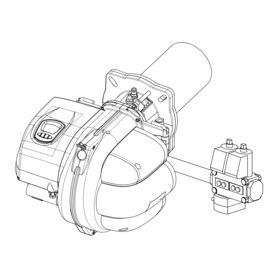
Page 8: Componenti Principali
COMPONENTI PRINCIPALI 20 21 8 LEGENDA 1 Motore 2 Cruscotto 3 Display 4 Spioncino 5 Coperchio presa aria 6 Gruppo valvola gas 7 Servomotore aria 8 Centralina 9 Contattore-relè motore 10 Boccaglio 11 Flangia bruciatore 12 Prelievo segnale aria 13 Regolazione anello 14 Pressostato aria 15 Isolante flangia 16 Testa di combustione... -
Page 9: Dimensioni
DIMENSIONI Fm - FM Modello Ø LMB G 300 BC LMB G 300 BL LMB G 450 BC LMB G 450 BL G 300 BC VCV-L 125 VCV-L 225 MBC 300 G 450 BC VCV-L 125 VCV-L 225 MBC 700... -
Page 10: Descrizione Gruppo Valvole
GRUPPO VALVOLE VCV L (lenta acensione) Corpo valvola VCV L pF: attacco tubo ca- mera combustione (eventuale) Pressostato gas di minima Tubo prelievo segnale aria (polietilene) Corpo valvola Tubo prelievo segnale gas (rigido) Tubo prelievo segnale aria (polietilene) pF: attacco tubo ca- Pressostato gas di mera combustione minima... -
Page 11: Curve Di Pressione/Portata
CURVE DI PRESSIONE / PORTATA Indicano la pressione del gas, in mbar, (nei vari punti della rampa gas) necessaria per ottenere una determinata portata in m /h. Le pressioni sono misurate con bruciatore in funzione e si intendono con camera di combustione a 0 mbar. - Page 12 Pe = Pressione a monte del gruppo valvole Pv = Pressione a valle rampa Pt = Pressione alla testa di combustione PG = Pressostato gas di minima ATTENZIONE: le prese di pressione gas Pt - Pv presentano uno spillo a vite di chiusura. Assicurarsi che le prese gas Pt - Pv siano chiuse durante il normale funzionamento.
-
Page 13: Ricevimento Del Prodotto
RICEVIMENTO DEL PRODOTTO Il bruciatore viene fornito protetto da un imballo di cartone o cartone / legno. AVVERTENZA I libretti di istruzione sono parte integrante dell’apparecchio e quindi si raccomanda di leggerli prima di installare ed avviare il bruciatore e, successivamente, di conservarli con cura. La busta documenti, posizionata all’interno dell’imballo, contiene il seguente materiale: - Libretto di installazione e manutenzione - Certificato di garanzia... -
Page 14: Montaggio Alla Caldaia
MONTAGGIO ALLA CALDAIA Il bruciatore viene fissato per mezzo della flangia, interponendo fra essa e la piastra della caldaia la guarnizione isolante in dotazione. Per la foratura della caldaia e il posizionamento delle viti di fissaggio, fare riferimento al disegno. Guarnizione isolante (n.2) Modello G 300 BC... -
Page 15: Montaggio Gruppo Valvole
MONTAGGIO GRUPPO VALVOLE VCV L (lenta accensione) Per fissare il gruppo valvole (fig. A) al bruciatore, utilizzare le 4 rondelle (a) e le 4 viti M8 x 20 in dotazione al gruppo valvole, facendo attenzione che la guarnizione di sughero/gomma (c) sia posizionata correttamente e non ci siano perdite di gas nell’accoppiamento. - Page 16 Per fissare il gruppo valvole (fig. A) al bruciatore, utilizzare le 4 rondelle (a) e le 4 viti M8 x 20 in dotazione al gruppo valvole, facendo attenzione che la guarnizione di sughero/gomma (c) sia posizionata correttamente e non ci siano perdite di gas nell’accoppiamento. Vite M8 x 30 Fig.
-
Page 17: Collegamenti Elettrici
COLLEGAMENTI ELETTRICI LEGGERE ATTENTAMENTE LE NORME GENERALI A PAGINA 3 - NEUTRO A TERRA: nel caso di rete di alimentazione con NEUTRO COLLEGATO A TERRA collegare il NEU- TRO della rete di alimentazione al NEUTRO dell’apparecchiatura. - NEUTRO ISOLATO: nel caso di rete di alimentazione con NEUTRO ISOLATO è necessario l’utilizzo di un tra- sformatore di isolamento. -
Page 18: Apparecchiatura
APPARECCHIATURA Caratteristiche generali - Filtro EMC e fusibile a bordo scheda. - Temporizzazioni stabili non influenzate da variazioni di tensione e/o temperature (gestione del sistema esegui- ta da microprocessore). - Protezione in caso di bassa/elevata tensione di alimentazione. - Monitoraggio funzionamento pressostato aria. Blocco non volatile. Reset remoto. - Funzionamento intermittente: arresto di regolazione e autodiagnosi ogni 24h. - Page 19 Tabella tempi Tempo di pre-ventilazione 20s (*) Tempo di pre-accensione 0,5s (*) Tempo di sicurezza 3s (**) Ritardo max. consenso pressostato aria prima di blocco 10s (***) Ritardo gestione regolatore di funzionamento Tempo di intervento allo spegnimento < 1s Temporizzazione massima durata segnale di fiamma parassita prima di blocco Tempo di post-ventilazione da 0 a 255 s Temporizzazioni limite pressioni tasto per sblocco...
- Page 20 sivo agendo solamente sul pulsante. Tramite pressione e rilascio del pulsante si passa allo stadio immediatamente successivo fino a raggiungere il secondo stadio; con ulteriore pressione si torna al precedente fino a tornare in posizione di primo stadio(nel caso di bruciatore modulante si passa dal minimo di modulazione al massimo di modulazione e viceversa). Durante la fase di funzionamento MANUALE il numero di lampeggi di colore giallo indicano lo stadio corrente di funzionamento ( 1 lampeggio = primo stadio o minimo di modulazione), (2 lampeggi = secondo stadio o massimo di modulazione).
-
Page 21: Ciclo Di Funzionamento
CICLO DI FUNZIONAMENTO Controllo bruciatore Accensione Alla chiusura del contatto di richiesta calore e verificato il corretto stato del contatto pressostato aria viene inserito il motore ventilatore e viene comandata in apertura totale la serranda aria. Raggiunta la totale apertura della serranda e verificata la commutazione del contatto pressostato aria ha inizio il tempo di pre-ventilazione durante il quale viene eseguito il test dell’amplificatore di fiamma e dei componenti associati a funzioni di sicurezza;... - Page 22 le chiusura corrispondente alla portata di avviamento (con afflusso gas sempre chiuso). c) Sequenza di formazione della fiamma di avviamento: si verifica l’eccitazione delle bobine relative alle elettro- valvole del gas ed il regolatore gas risulta parzialmente aperto in relazione alla pressione dell’aria di avviamento. d) Sequenza di passagio alla fiamma principale o secondo stadio: il servocomando aziona l’apertura della aria (fino alla massima portata di taratura) il cui aumento di pressione provoca l’incremento graduale della portata gas.
- Page 23 Diagramma accensione Fase di accensione con controllo di tenuta abilitato...
- Page 24 Diagramma di funzionamento a 2 stadi progressivi Con termostato Tmf di alta / bassa fiamma...
- Page 25 Diagramma di funzionamento a modulazione continua...
-
Page 26: Interfaccia Utente
INTERFACCIA UTENTE Tramite il pannello controllo e comando è possibile mo- nitorare lo stato del bruciatore, accedere ai menù di dia- gnostica e configurazione del sistema e procedere allo sblocco dell’apparecchiatura. Il pannello di controllo e comando è composto da un LCD con area visiva retroilluminata e 4 tasti funzione. - Page 27 Visualizzazione Il pannello di controllo e comando rende disponibili 3 modalità di visualizzazione: NORMALE: in questa modalità appaiono sul display le icone relative allo stato di funzionamento del bruciatore. Se non sono presenti anomalie appaiono sul display il numero di cicli di accensione eseguiti dal bruciatore ed il numero di ore complessive di funzionamento.
- Page 28 In presenza invece di anomalie verranno invece visualizzati contemporaneamente il codice dell’anomalia (vedi tabella 1) ed il tipo (volatile o non volatile). NON VOLATILE VOLATILE Codice Codice anomalia anomalia Codice e icona anomalia Retroilluminazione lampeggiante lampeggianti CODICE ANOMALIA SIGNIFICATO NON VOLATILE Blocco mancata accensione Blocco fiamma parassita Blocco per numero massimo spegnimenti...
- Page 29 Nel caso di attivazione di funzioni speciali viene visualizzata la funzione in esecuzione. Lampeggio Funzionamento modo manuale: Arresto temporaneo:...
-
Page 30: Accesso Ai Menu
ACCESSO AI MENU’ PROCEDURA DI ABILITAZIONE ACCESSO AI MENU’ Per poter abilitare la visualizzazione e conseguente gestione dei menu citati in precedenza è necessario, durante la fase di visualizzazione normale, eseguire la seguente procedura: a) PRESSIONE PROLUNGATA DEL TASTO “ ”... - Page 31 MENU’ INFO Se bruciatore bistadio il MENU INFO è organizzato come da tabella 2. Se bruciatore modulante il MENU INFO è organizzato come da tabella 2b. Bruciatore bistadio MENU RappResentazione infoRMazioni Ore di funzionamento bruciatore 1° stadio Ore di funzionamento bruciatore 2° stadio CONTAORE Ore totali di funzionamento bruciatore Azzeramento contaore...
- Page 32 Bruciatore modulante MENU RappResentazione infoRMazioni CONTAORE Ore totali di funzionamento bruciatore Azzeramento contaore Cicli funzionamento bruciatore CONTACICLI Cicli mancata accensione del bruciatore Azzeramento contacicli MENU INFO CONSUMI COMBUSTIBILE Intensità segnale di fiamma SEGNALE DI FIAMMA Posizione attuale servomotore serranda aria SERVOMOTORE SERRANDA ARIA Cicli di apertura totale servomotore serranda aria Frequenza di rete...
- Page 33 Così facendo si accede alla visualizzazione di conferma consenso azzeramento di durata 5s. lampeggio Una ulteriore pressione del tasto i durante questa visualizzazione determina l’azzeramento di tutti i contatori rela- tivi alle ore di funzionamento ed il ritorno alla visualizzazione ore di funzionamento primo stadio Contacicli Vengono visualizzate i cicli di funzionamento del bruciatore rispettivamente in primo e in secondo stadio (cicli di funzionamento totali del bruciatore equivalgono ai cicli primo stadio).
- Page 34 Una ulteriore pressione del tasto i durante questa visualizzazione determina l’azzeramento di utti i contatori rela- tivi ai cicli bruciatore ed il ritorno alla visualizzazione cicli di funzionamento primo stadio. Consumi combustibile (Non gestito se BRUCIATORE MODULANTE) Tramite il MENU INSTALLATORE è possibile impostare il consumo orario di combustibile rispettivamente del primo e del secondo stadio.
- Page 35 Segnale di fiamma Viene visualizzato il valore in uA del segnale di fiamma. Segnale di fiamma in micro A Nel caso in cui il segnale di fiamma letto superi di 10 volte il valore di soglia rilevazione segnale di fiamma, la visualizzazione risulta: Lampeggio Servomotore serranda aria...
- Page 36 Vengono visualizzati inoltre i cicli di apertura totale eseguiti dal servomotore. Per azzerare il contatore cicli apertura servomotore premere il tasto i durante la seguente visualizzazione: lampeggio Così facendo si accede alla visualizzazione di richiesta conferma azzeramento di durata 5s. Una ulteriore pressione del tasto i determina l’azzeramento del contatore cicli servomotore ed il ritorno alla visualizzazione cicli apertura servomotore.
- Page 37 enù stoRiCo anoMaLie Il MENU HIST è organizzato come da tabella 3. MENU RappResentazione infoRMazioni Storico anomalie per ore di funzionamento (Posizione 1/8) Storico anomalie per ore di funzionamento (Posizione 2/8) Storico anomalie per ore di funzionamento (Posizione 3/8) Storico anomalie per ore di funzionamento (Posizione 4/8) STORICO ANOMALIE (VISUALIZZAZIONE PER ORE) Storico anomalie per ore di funzionamento (Posizione 5/8)
- Page 38 Qui di seguito un esempio. (In posizione 1 blocco mancata accensione verificatosi dopo 99 ore di funzionamento del bruciatore). STORICO ANOMALIE (VISUALIZZAZIONE PER CICLI) E’ possibile visualizzare uno storico relativo alle ultime anomalie verificatesi. Lo storico tiene traccia delle ultime 8 anomalie ( tipo e codice anomalia) e dei rispettivi cicli di funzionamento del bruciatore.
- Page 39 Così facendo si accede alla visualizzazione di richiesta conferma azzeramento di durata 5s. lampeggio Una ulteriore pressione del tasto i determina l’azzeramento dello storico anomalie ed il ritorno alla visualizzazione storico posizione 1 per ore di funzionamento. enù paRaMetRi Il MENU PARAM è organizzato come da tabella 4. MENU RappResentazione VaLoRi iMpostaBiLi...
- Page 40 Tramite pressione del tasto i si accede alla modalità MODIFICA VALORE PARAMTERO, durante la quale il valore del parametro visualizzato lampeggia. In modalità MODIFICA VALORE PARAMETRO utilizzare i tasti + e – per modificarne il valore. Per memorizzare il valore corrente visualizzato premere il tasto i . Per uscire da questa modalità...
- Page 41 del bruciatore e non in fase di regolazione durante il funzionamento. Se non si desidera usufruire della funzione appena descritta è sufficiente impostare a 0 il parametro in oggetto. Tramite pressione del tasto i si accede alla modalità MODIFICA VALORE PARAMTERO, durante la quale il valore del parametro visualizzato lampeggia.
- Page 42 FUNZIONAMENTO MODO MANUALE Questo parametro permette di attivare la fase di FUNZIONAMENTO MANUALE PER TARATURA BRUCIATORE BRUCIATORE BISTADIO BRUCIATORE MODULANTE Tramite pressione del tasto i si accede alla modalità MODIFICA VALORE PARAMTERO, durante la quale il valore del parametro visualizzato lampeggia. In modalità...
- Page 43 Valore parametro (da 0 a 255) Tramite pressione del tasto i si accede alla modalità MODIFICA VALORE PARAMTERO, durante la quale il valore del parametro visualizzato lampeggia. In modalità MODIFICA VALORE PARAMETRO utilizzare i tasti + e – per modificarne il valore. Per memorizzare il valore corrente visualizzato premere il tasto i .
- Page 44 REGOLAZIONI Regolazione anello aria Per regolare la posizione dell’anello aria, agire sulla vite A, in senso orario aumenta quantità aria, in senso antio- rario diminuisce. Vite di regolazione A Anello aria (otturatore) Posizione massima apertura Posizione minima apertura...
- Page 45 Posizionamento elettrodi E’ previsto un elettrodo per l’accensione, ed un elettrodo di controllo fiamma: essi non debbono per alcun motivo toccare il deflettore o altre parti metalliche in quanto perderebbero la loro funzione, compromettendo il funziona- mento del bruciatore. É opportuno verificare la corretta posizione dopo ogni intervento sulla testata. 30°...
- Page 46 Regolazione pressostato gas di minima Il pressostato gas di minima ha il compito di impedire l’avviamento del bruciatore o di fermarlo se è in funzione. Se la pressione del gas non è la minima prevista, esso va tarato al 40% più basso del valore della pressione gas, che si ha in funzionamento con la portata massima.
- Page 47 Descrizione e regolazione valvola gas VCV Regolatore di rapporto variabile per il blocco e per la regolazione del rapporto della pressione gas/ aria in bruciatori modulanti. Il rapporto si può regolare da 0,6:1 a 3:1. Con la pressione di controllo della camera di combustione pF si possono correggere le variazioni di pressione della camera stessa.
- Page 48 VAV: installazione della linea di controllo dell’aria pL e della linea di controllo della camera di combu- stione pF Disponibili collegamenti a vite per tubi flessibili in plastica (Ø interno 3,9). ATTENZIONE! Non smontare e sostituire. Posare la linea di controllo dell’aria pL e la linea di controllo della camera di combustione pF sulle prese di misura della pressione dell’aria e della camera di combustione.
- Page 49 - Chiudere tutte le prese di misura – non chiudere il raccordo pF eventualmente non utilizzato. - Si raccomanda di avviare il bruciatore con una potenza superiore a quella della portata minima (por- tata di avviamento) in modo da ottenere una fiamma costante. Calcolo - Senza collegamento della pressione di controllo della ca- mera di combustione pF:...
- Page 50 Descrizione e regolazione valvola gas MBC Il regolatore combinato per gas-aria, permette una miscelazione ottimale per bruciatori. Ciò vale per il funziona- mento a modulazione e modulazione continua a più stadi. Funzionamento - Flusso del gas 1. Se le valvole 1 e 2 sono chiuse, il vano a rimane sotto pressione di entrata. 2.
- Page 51 CONTROLLI DEL FUNZIONAMENTO Controllo combustione Al fine di ottenere i migliori rendimenti di combustione e, nel rispetto dell’ambiente, si raccomanda di effettuare, con gli adeguati strumenti, controllo e regolazione della combustione. Valori fondamentali da considerare sono: ● CO . Indica con quale eccesso d’aria si svolge la combustione; se si aumenta l’aria, il valore di CO % diminui- sce, e se si diminuisce l’aria di combustione il CO aumenta.
- Page 52 Verifiche preventive a) Eseguire un ciclo di funzionamento con elettrodo di rivelazione scollegato dall’apparecchiatura: verificare l’esecuzione di un arresto di blocco al termine del tempo di sicurezza! b) Eseguire un ciclo di funzionamento con elettrodo di rivelazione collegato direttamente ad un morsetto di terra: verificare l’esecuzione di un arresto di blocco al termine del tempo di sicurezza! c) Eseguire un ciclo di funzionamento e, verificata l’accensione del bruciatore, chiudere l’alimentazione di gas al fine di ottenere uno spegnimento fiamma:...
- Page 53 Il controllo fiamma avviene tramite elettrodo di rivelazione, sfruttando il fenomeno della ionizzazione. Il circuito amplificatore di fiamma è sensibile alle variazioni della componente continua (DC) della corrente del segnale di fiamma. CIRCUITO DI TEST DELL’ AMPLIFICATORE Massima lunghezza cavo rivelazione fiamma: 1m Un eventuale corto circuito tra l’elettrodo di rivelazione e terra non permette la lettura del segnale di fiamma;...
- Page 54 il valore Qs è ricavato da: dove Q1 è la portata espressa in litri liberata in n° 10 partenze nel tempo di sicurezza. Ts1 è la somma del tempo di sicurezza effettivo nelle 10 partenze. Qn è la potenza nominale. Per ricavare Q1 occorre operare come segue: ●...
- Page 55 E’ ora possibile accedere alle viti (2) che bloccano il coperchio quadro elettrico (B). Svitare quindi le viti (2) e sol- levare il coperchio (B) facendo attenzione ai ganci di ploccaggio del coperchio posti sul lato posteriore del quadro elettrico. Ganci Presa aria - manutenzione bandella aria Per accedere alla bandella aria e al sistema di chiusura aria, occorre svitare la vite (3) che blocca il coperchio...
- Page 56 Apertura bruciatore e accesso alla testa di combustione e regolazione dell’anello aria Per accedere alla testa di combustione e per regolare l’anello dell’aria, occorre svitare le due viti (4). Quindi sfilare il perno destro (DX) o sinistro (SX) a seconda della necessità e della posizione del gruppo valvole (esempio della figura perno DX).
- Page 57 Aperto il bruciatore svitare il raccordo presa gas Pt e sfilarlo dalla sede. E’ possibile ora procedere all’estrazione della testa di combustione. Estrazione testa di combustione Guarnizione tenuta gas ATTENZIONE. Durante la fase montaggio della testa di combustione nella propria sede controllare che la guar- nizione di tenuta gas evidenziata in figura sia ben posizionata.
- Page 58 Irregolarità di funzionamento DIFETTO CAUSA RIMEDIO Controllare i fusibili della linea di alimentazione. Controllare la linea Mancanza di energia elettrica dei termostati e del pressostato Il bruciatore non si avvia Controllare l’apertura dei disposi- Non arriva gas al bruciatore tivi d’intercettazione posti lungo la tubazione di alimentazione Controllare il funzionamento delle Le valvole del gas non aprono...
- Page 59 Congratulations on your excellent choice Thank you for your preference towards our products.LAMBORGHINI CALORECLIMA is a Company that has daily involvement in the research for innovative technical solutions, able to satisfy all needs. The constant presence of out products on the Italian and international market is guaranteed by a capillary network of Agents and Authorised dealers.
-
Page 60: General Standards
GENERAL STANDARDS • This booklet constitutes an integral and essential part of the product and should be supplied to the installer. Read carefully the instructions contained in this booklet as they provide important directions regarding the safety of installation, use and maintenance. Preserve this booklet with care for any further consultation. - Page 61 • On noticing the smell of gas do not touch any electrical switch. Open all doors and windows. Shut off the gas cocks. Call qualified personnel. • The room where the burner is located must have the openings required by local regulations in force. Should you have any doubts as to the circulation of the air in the room, then you should first measure the CO figure with the burner working at its maximum delivery and with the room ventilated solely by means of the openings...
-
Page 62: Description
• The length of the cables used must enable the burner to be opened, as well as the boiler door. • After removing the packaging materials, check the content integrity and make sure that no damages have occured during transportation. In case of doubt, do not use the burner and contact the supplier. •... -
Page 63: Technical Data
TECHNICAL DATA LMB G 300 BC LMB G 450 BC Model LMB G 300 BL LMB G 450 BL Type Two-stage progressive or modulating Functioning Intermittent Regulation Air/gas proportional valve Maximum heat output (natural gas) Minimum heat output (natural gas) -
Page 64: Main Components
MAIN COMPONENTS 1 Motor 20 21 8 2 Control panel 3 Display 4 Inspection hole 5 Air vent lid 6 Gas valve 7 Air servo-motor 8 Control unit 9 Contactor-motor relay 10 Flow nozzle 11 Burner flange 12 Air vent 13 Ring regulation 14 Air pressure switch 15 Flange insulation... -
Page 65: Dimensions
DIMENSIONS Fm - FM Model Ø LMB G 300 BC LMB G 300 BL LMB G 450 BC LMB G 450 BL G 300 BC VCV-L 125 VCV-L 225 MBC 300 G 450 BC VCV-L 125 VCV-L 225 MBC 700... -
Page 66: Valves Unit Description
VALVES UNIT VCV L (slow opening) VCV L valve body chamber combustion signal (possible) Minimum gas pressu- re pressure switch Air signal withdrawal pipe (polyethylene) Valve body Gas signal withdrawal pipe (rigid) Gas signal withdrawal pipe (polyethylene) chamber combustion signal Minimum gas pressu- (possible) re pressure switch... -
Page 67: Pressure/Flow Rate Curves
PRESSURE/FLOW RATE CURVES They indicate the gas pressure in mbar, (in the various points of the gas ramp) necessary to obtain a determined flow rate in m3/h. The pressures are measured with the burner functioning and are intended with combustion chamber at 0 mbar. - Page 68 Pe = Pressure upstream from the valves unit Pt = Pressure at the combustion head Pv = Pressure downstream of the ramp PG = Minimum gas pressure pressure switch ATTENTION: the Pt-Pv gas pressure outlets have a screw closing pin. Ensure that the Pt - Pv gas outlets are closed during normal operation.
-
Page 69: Receiving The Product
RECEIVING THE PRODUCT The burner is supplied protected by cardboard or cardboard/wood packaging. WARNING The instruction manuals are an integral part of the appliance and therefore must be read before installing and starting the burner and must be kept with care. The documents envelope, positioned inside the packaging, contains the following material: - Installation and maintenance book - Warranty certificate... -
Page 70: Boiler Assembly
BOILER ASSEMBLY The burner is fixed by the flange, placing the supplied insulated gasket between the plate and the boiler. For drilling of the boiler and positioning of the fastening screws, refer to the diagram. Insulating gasket (n.2) Model G 300 BC G 300 BL G 450 BC G 450 BL... -
Page 71: Valves Unit Assembly
VALVES UNIT ASSEMBLY VCV L (slow opening) To fix the valves unit (fig. A) to the burner, use the 4 washers (a) and the 4 M8 x 20 screws supplied with the val- ves unit, paying attention that the cork/rubber gasket (c) is positioned correctly and there are no gas leaks in the coupling. - Page 72 To fix the valves unit (fig. A) to the burner, use the 4 washers (a) and the 4 M8 x 20 screws supplied with the val- ves unit, paying attention that the cork/rubber gasket (c) is positioned correctly and there are no gas leaks in the coupling.
-
Page 73: Electric Connections
ELECTRIC CONNECTIONS READ THE GENERAL STANDARDS ON PAGE 60 CAREFULLY - NEUTRAL TO EARTH: in the case of power supply mains with NEUTRAL CONNECTED TO EARTH connect the mains power supply NEUTRAL to the appliance NEUTRAL. - INSULATED NEUTRAL: in the case of mains power supply with INSULATED NEUTRAL it is necessary to use an insulation transformer. -
Page 74: Appliance
APPLIANCE Main features - EMC filter on the board. Protection fuse on the board. - Stable timers not affected by the voltage and/or temperature changes (system management by microproces- sor). - Protection in case of low/high voltage power supply. - Monitoring of air pressure switch functioning. Non-volatile block. remote reset; - Intermittent functioning: regulation and self-diagnosis stop every 24h. - Page 75 Table of times Pre-ventilation time 20s (*) Pre-ignition time 0.5s (*) Safety time 3s (**) Air pressure switch consent max. delay before block 10s (***) Functioning regulator management delay Intervention time to switch-off < 1s Parasite flame signal duration maximum timing before block Post-ventilation time from 0 to 255 s Key pressing limit timing for release...
- Page 76 possible to pass from one functioning stage to the next by just acting on the button. By pressing and releasing the button, pass to the next intermediate stage until reaching the second stage. Press again to return to the previous until reaching the first stage position (in the case of modulating boiler, pass from minimum modulation to maximum modulation and vice versa).During the MANUAL functioning phase, the number of yellow flashings indicate the current functioning status (1 flash = first stage or minimum modulation), (2 flashes = second stage or maximum modulation).If the signal becomes flashing red during MANUAL functioning, check...
-
Page 77: Functioning Cycle
FUNCTIONING CYCLE Burner control Ignition On closure of the heat request contact and when the correct status of the air pressure contact has been verified, the fan motor is inserted and the air damper total opening is controlled.On reaching total opening of the damper and switch-over of the air pressure switch contact has been verified, the pre-ventilation time starts during which the flame amplifier test is performed along with components associated to safety functions. - Page 78 corresponding to start-up flow rate (with gas flow always closed). c) Formation sequence of the start-up flame: the coils relative to the gas solenoid valves are excited and the gas regulator is partially open in relation to the start-up air pressure. d) Passage sequence to the main flame or second stage: the servo-control activates the opening of the air (up to maximum flow rate calibration) whose increase in pressure causes the gradual increase of the gas flow rate.
- Page 79 Ignition diagram Ignition phase with sealing control enabled...
- Page 80 Two-stage progressive functioning diagram With Tmf thermostat with high/low flame...
- Page 81 Diagram of functioning with continuous modulation...
-
Page 82: User Interface
USER INTERFACE The control and command panel can be used to monitor the status of the burner, access the diagnostic and confi- guration menus of the system and release the appliance. The control and command panel is composed of an LCD with back-lit display area and 4 function keys Icon meaning ICON... - Page 83 Display The control and command panel makes 3 display methods available: NORMAL: in this mode, icons appear on the display that are relative to the burner functioning state.If there are no ano- malies present, the display shows the number of ignition cycles performed by the burner and the total number of functioning hours.If an anomaly occurs, the display shows the relative code and signals the type of anomaly, (volatile or non-volatile).
- Page 84 However, if anomalies are present, the anomaly code (see table 1) and the type of anomaly (volatile or non- volatile) will be displayed at the same time. NON VOLATILE VOLATILE Anomaly Anomaly code code Flashing code and anomaly Flashing back-light icon CODICE ANOMALIA SIGNIFICATO...
- Page 85 If special functions are activated, the function in progress is displayed. Manual functioning mode: Flashing Temporary shutdown:...
-
Page 86: Access To The Menus
ACCESS TO THE MENUS MENU ACCESS ENABLING PROCEDURE In order to enable the display and consequent management of the menus stated previously, during the normal display phase it is necessary to follow the procedure given: a) PROLONGED PRESSING OF KEY “ ”... - Page 87 INFO MENU If the burner is two-stage, the INFO MENU is organised as per table 2. If the burner is modulating the INFO MENU is organised as per table 2b. Two-stage burner MENU RepResentation infoRMation 1st stage burner functioning hours 2nd stage burner functioning hours TIMER Burner total functioning hours...
- Page 88 Modulating burner MENU RepResentation infoRMation TIMER Burner total functioning hours Timer reset Burner functioning cycles CYCLES-COUNTER Burner no ignition cycles Cycle-counter reset MENU INFO FUEL CONSUMPTION Flame signal intensity Air damper servo-motor current position FLAME SIGNALS Air damper servo-motor total opening cycles AIR DAMPER SERVO-MOTOR Servo-motor cycles reset Electrical frequency...
- Page 89 By doing this, access the reset consent confirmation display with duration of 5s. flashing Pressing the key again during this display determines the reset of all meters relative to the functioning hours and the return to first stage functioning hours display. Cycles-counter The burner functioning cycles are displayed respectively in first and second stage (total functioning cycles of the burner are equal to the first stage cycles).(In the case of modulating burner, only the total functioning cycles of the...
- Page 90 Pressing the key again during this display determines the reset of all meters relative to burner cycles and the return to first stage functioning cycles display. Fuel consumption (Not managed if MODULATING BURNER) Using the INSTALLER MENU it is possible to set the hourly fuel consumption respectively of the first and second stages.(Unit of measurement: m3/h).
- Page 91 Flame signal The flame signal value is displayed in uA. Flame signal in micro A If the flame signal read should exceed the flame signal detection threshold value by 10 times, the display is: Flame signal in micro A Air damper servo-motor The current position of the air damper servo-motor is displayed (closure total, first stage, total opening or second stage).
- Page 92 The total opening cycles performed by the servo-motor are also displayed. To reset the servo-motor opening cycles-counter, press the key i during the following display: flashing By doing this, access the reset request confirmation display with duration of 5s. Pressing the key again determines the reset of the servo-motor cycle meter and the return to the servo-motor opening cycles display.
- Page 93 noMaLies LoG Menu The HIST MENU is organised as per table 3. MENU RappResentazione infoRMazioni Anomalies log per functioning hours (Position 1/8) Anomalies log per functioning hours (Position 2/8) Anomalies log per functioning hours (Position 3/8) Anomalies log per functioning hours (Position 4/8) ANOMALIES LOG (DISPLAY BY HOURS) Anomalies log per functioning hours (Position 5/8)
- Page 94 An example is given below. (In position 1 no ignition block occurring after 99 burner functioning hours). ANOMALIES LOG (DISPLAY BY CYCLES) It is possible to display a log relative to the last anomalies occurring. The log keeps trace of the last 8 anomalies (anomaly code and type) and of the respective burner functioning cycles.
- Page 95 By doing this, access the reset request confirmation display with duration of 5s. flashing Pressing the key again determines the reset of the anomalies log and the returnto the position 1 log display for functioning hours. aRaMeteRs Menu The PARM MENU is organised as per table 4. MENU RappResentation settaBLe VaLues...
- Page 96 Press key i to access the PARAMETER VALUE MODIFICATION mode, during which the value of the parameter displayed flashes. In MODIFY PARAMETER VALUE mode, use the + and – keys to modify the value.Press key i to memorise the current value displayed.To exit this mode without memorising the value, press key R or wait 10s without pressing the keys.
- Page 97 displayed flashes. In MODIFY PARAMETER VALUE mode, use the + and – keys to modify the value. Press key i to memorise the current value displayed.To exit this mode without memorising the value, press key R or wait 10s without pressing the keys. SECOND STAGE SOLENOID VALVE ADVANCED ACTIVATION (Not managed if MODULATING BURNER) It is possible to introduce an advance on the second stage solenoid valve activation.
- Page 98 MANUAL FUNCTIONING MODE This parameter allows to activate the MANUAL FUNCTIONING FOR BURNER CALIBRATION phase TWO-STAGE BURNER MODULATING BURNER Press key i to access the PARAMETER VALUE MODIFICATION mode, during which the value of the parameter displayed flashes. In MODIFY PARAMETER VALUE mode, use the + and – keys to modify the value. Press key i to memorise the current value displayed.To exit this mode without memorising the value, press key R or wait 10s without pressing the keys.
- Page 99 Parameter value (da 0 a 255) Press key i to access the PARAMETER VALUE MODIFICATION mode, during which the value of the parameter displayed flashes.In MODIFY PARAMETER VALUE mode, use the + and – keys to modify the value. Press key i to memorise the current value displayed.To exit this mode without memorising the value, press key R or wait 10s without pressing the keys.
- Page 100 REGULATIONS Combustion head shutter regulation To adjust the position of the ring air, turn the screw in, clockwise to increase air volume, counterclockwise to decrease. Regulation srew A Air ring (shutter) Maximum opening position Minimum opening position...
- Page 101 Electrodes positioning An electrode is provided for ignition and one for flame control: these must not touch the deflector or other metal parts for any reason as they would loose their function, compromising burner functioning. It is good practice to check the correct position after every intervention on the head. NATURAL GAS 30°...
- Page 102 Minimum gas pressure pressure switch The gas minimum pressure pressure switch prevents burner start-up of stops it if it is functioning. If the gas pres- sure is not the minimum envisioned, it must be calibrated at 40% lower than the value of the gas pressure, which functions with maximum flow rate.
- Page 103 Description and regulation of gas valve VCV Variable ratio regulator for the block and regulation of the gas/air pressure ratio in modulating burners. The ratio can be regulated from 0.6:1 to 3:1. Using the control pressure of the combustion chamber pF it is possible to correct the pressure varia- tions of the chamber itself.
- Page 104 VAV: installation of the air control line pL and the control line of the combustion chamber pF Screw connections for plastic flexible hoses are available (Ø internal 3.9). ATTENTION! Do not disassemble and replace. Lay the air control line pL and the combustion chamber line pF on the measuring points of the air pres- sure and combustion chamber.
- Page 105 Calculation - Without connection of the control pressure of the combustion chamber pF: pG = V × pL + N - With connection of the control pressure of the combustion chamber pF: (pG – pF) = V × (pL – pF) + N Control of the regulation capacity - Take the burner to maximum flow rate.
- Page 106 Description and regulation of gas valve MBC MBC 700 The servo pressure regulator permits optimal mixture formation in forced air burners and premix burners in con- junction with mechanical or electronic integrated gas-air regulation units; this applies to modulating and multistage floating operating mode.
- Page 107 FUNCTIONING CONTROLS Combustion control In order to obtain the best combustion yield and with respect to the environment, it is recommended to use suitable instruments to control and regulate combustion. Fundamental values to consider are: ● CO . It indicates with which air excess combustion takes place; if the air increases, the % value of CO decre- ases, and if the combustion air decreases the CO increases.
- Page 108 obtain flame switch-off:check the repetition of a cycle and consequent block shutdown caused by no ignition at the end of the safety time! d) Carry out a functioning cycle and, when burner ignition has been verified, open the contact relative to the air pressure switch:verify the immediate switch off of the solenoid valve and consequent block shutdown caused by air pressure switch anomaly after 10s! e) Close the air pressure switch contact and then make a functioning request:verify the non-activation of the motor...
- Page 109 The flame amplified circuit is sensitive to the variations of the continuous component (DC) of the flame signal current. TEST CIRCUIT Maximum length of flame detection cable: 1mAny short circuit between the detection electrode and earth does not allow the flame signal to be read. The appliance will perform a lock shutdown at the end of the safety time. Repetition of the cycle in case the flame switches off in normal working position: If the flame goes out in normal working position, the appliance repeats the start-up cycle (max 3 cycle repetitions);...
- Page 110 the value Qs is obtained from: where Q1 is the flow rate expressed in litres freed in n° 10 start-ups in the safety time. Ts1 is the sum of the effective safety time in the 10 start-ups. Qn is the nominal power. To obtain Q1, operate as follows: ●...
- Page 111 It is now possible to access the screws (2) that block the electric control board lid (B). Loosen the screws (2) and lift the lid (B) paying attention to the lid blocking hooks positioned don the rear of the electric control board. Hooks Air vent - air flap maintenance To access the air flap and the air closure system, loosen the screw (3) that blocks the air vent lid (C).
- Page 112 Burner opening and access to the combustion head and regulation of the air ring To access the combustion head and to regulate the air ring, loosen the two screws (4). Slide out the right (RH) or left (LH) pin according to necessity and the position of the valves unit (RH pin in the example). At this point it is possible open the burner by turning the pin remaining in the seat.
- Page 113 When the burner is open, loosen the gas tapping point fitting Pt and extract it from the seat. The combustion head can now be removed. Combustion head extraction Gas seal gasket ATTENTION. During the assembly phase of the combustion head in its seat, control that the gas sealing gasket, highlighted in the figure, is well positioned...
- Page 114 Functioning irregolarity DEFECT CAUSE REMEDY Control the power supply line fu- No electrical power ses. Control the thermostats and gas pressure switch lines The burner does not start-up Check the opening of the shut-off Gas does not reach the burner devices positioned along the sup- ply piping.
- Page 116 Le illustrazioni e i dati riportati sono indicativi e non impegnano. Lamborghini Caloreclima si riserva il diritto di apportare senza obbligo di preavviso tutte le modifiche che ritiene più opportune per l’evoluzione del prodotto. The illustrations and data given are indicative and not binding. Lamborghini Caloreclima reserves the right to make all modifications it deems appropriate for improvement of the product without forewarning.
Need help?
Do you have a question about the LMB G 300 BC and is the answer not in the manual?
Questions and answers