Table of Contents
Advertisement
Quick Links
Advertisement
Table of Contents

Related Manuals for PSI Matrix PP204


Summary of Contents for PSI Matrix PP204
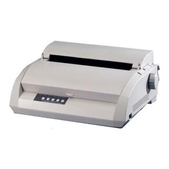
- Page 1 User´s manual PP204 / PP205 Benutzerhandbuch PP204 / PP205 englisch...
- Page 2 IMPORTANT NOTE TO USERS READ THE ENTIRE MANUAL CAREFULLY BEFORE USING THIS PRODUCT. INCORRECT USE OF THE PRODUCT MAY RESULT IN INJURY OR DAMAGE TO USERS, BYSTANDERS OR PROPERTY. While Printer Systems international has sought to ensure the accuracy of all information in this manual, PSi assumes no liability to any party for any damage caused by any error or omission contained in this manual, its updates or supplements, whether such errors or omissions result from negligence, accident, or any other cause.
- Page 3 NOTES 1. Testing of this equipment was performed on model number PP204 or PP205. 2. The use of a nonshielded interface cable with the referenced device is prohibited.
- Page 4 Canada. Notice for German Users Bescheinigung des Herstellers/Importeurs Hiermit wird bescheinigt, daß der/die/das • PP204 • PP205 "Warning: This is an EN 55022 Class A product. In a domestic environment this product may cause radio interference in which case the user may be required to take adequate measures."...
- Page 5 CE Declaration This product sold in Europe conforms to the standard in accordance with EC Directives. User's Manual...
- Page 6 (100-120 or 220-240 VAC). User manual PP20x November 2014 Copyright © PSi Matrix GmbH Printed in Germany. All rights reserved. No part of this manual may be reproduced or translated, stored in a database or retrieval system, or transmit-...
- Page 7 ABOUT THIS MANUAL Thank you for buying the PSi PP204/PP205 dot matrix printer. You can expect years of reliable service with very little maintenance. This manual explains how to use your printer to full advantage. It is written for both new and experienced printer users.
- Page 8 ORGANIZATION This manual is organized as follows: Quick Reference summarizes everyday printer operations. After you become familiar with the printer, use this section as a memory aid. Chapter 1, Introduction, introduces the printer and identifi es key features and options that enhance the printer’s capabilities. Chapter 2, Setting Up, gives step-by-step procedures for setting up the printer for immediate use and identifi es the main parts of the printer.
- Page 9 At the end of this manual, you will fi nd several appendixes, a glossary, and an index. Appendix A gives order numbers for printer supplies, options, and publications. Other appendixes provide additional technical information about the printer. CONVENTIONS Special information, such as warnings, cautions, and notes, are indicated as follows: WARNING A WARNING indicates that personal injury may result if you do not follow a...
- Page 10 TABLE OF CONTENTS Quick Reference..........QR-1 CHAPTER1 INTRODUCTION Features ................ 1–1 Options ................1–2 User's Manual...
-
Page 11: Table Of Contents
Selecting a Good Location ........... 2–1 Checking Options and Supplies ......2–5 Installing the Cut Sheet Stand ......... 2–6 Getting Acquainted With Your Printer ......2–10 Testing the Printer ......... 2–13 Printing the Self-Test ..........2–14 Selecting a Parallel Interface Cable ...... 2–19 Selecting a USB Cable .......... - Page 12 CHAPTER4 PRINTING Selecting Print Features ..........4–1 Using Commercial Software ........4–2 Using the Control Panel .......... 4–2 Selecting MENU1 or MENU2 ......... 4–3 Starting or Stopping Printing ........4–5 Starting Printing ............4–5 Stopping Printing ............ 4–5 Resuming from a Paper-Out ........4–5 Printing the remaining lines on a page ....
- Page 13 Resetting Defaults ............. 5–50 Resetting Power-On Defaults ....... 5–50 Resetting Factory Defaults ........5–50 Resetting Factory Defaults in MENU1 and MENU2... 5–50 Using the Diagnostic Functions ......... 5–51 Printing the Self-Test ..........5–52 Procedure ............. 5–52 Printing Hex Dumps ..........5–53 Procedure .............
- Page 14 Tips for Clearing a Jammed Sheet from the Printer ..7–6 Operating Problems ..........7– Printer Failures ............7– Diagnostic Functions ..........7– Getting Help ............... 7– CHAPTER8 INSTALLING OPTIONS ............8- Loading Paper for the Self-Test ......2–13 CHAPTER2 SETTING UP Connecting the Printer to Your Computer ....
- Page 15 APPENDIX C COMMAND SETS Fujitsu DPL24C PLUS ..........C–2 Factory Default Settings ........C–15 IBM Proprinter XL24E Emulation ......C–18 Epson ESC/P2 Emulation .........C–23 User's Manual...
- Page 16 APPENDIX D INTERFACE INFORMATION Parallel Interface ............D–1 Compatible Mode ...........D–2 Nibble Mode ............D–4 Data Transmission Timing ........D–6 Serial Interface ............D–7 Serial Options............D–8 Cable Wiring............D–8 Serial Protocols ............D–10 USB Interface ............D–11 ............D–11 LAN Interface ............D–12 APPENDIX E COMMAND SETS Character Sets 1and 2 (DPL24C PLUS and IBM XL24E Emulation)....
- Page 17 QUICK REFERENCE QUICK REFERENCE Quick Reference is written for experienced users — users who are familiar with how the printer works, but who may need to refresh their memory Intro occasionally. Only the printer’s normal (non-setup) ducti mode is covered. For details on setup mode, see Chapter 5. Normal mode operation includes everyday operations, such as paper handling and font selection.
- Page 18 QUICK REFERENCE Printer Operations (Normal Mode) : Operation can be performed when the printer is in this state. — : Operation cannot be performed when the printer is in this state. N/A : Does not apply. Operation Online Offline Required Response —...
- Page 19 INTRODUCTION Refer ence Quic INTRODUCTION Congratulations on purchasing this printer. This printer is a compact, versatile printer that offers maximum compatibility with today’s software packages and personal computers. The 24-wire print head provides crisp, clear printing for business, office, and home environments.
- Page 20 INTRODUCTION • Multiple fonts. The printer has nineteen resident fonts: Ten bit-map fonts -- Courier 10, Pica 10, Prestige Elite 12, Boldface PS, OCR-B 10, OCR-A 10, Correspondence, Compressed, Draft, and High-speed Draft and nine outline fonts -- Timeless, Nimbus Sans, and Courier, each in upright, italic, and bold.
-
Page 21: Selecting A Good Location
SETTING UP Refe renc SETTING UP Quic Your new printer is easy to install and set up. This chapter tells you how to set up the printer and start printing right away. If this is your first printer, you should read the entire chapter before attempting to use the printer. - Page 22 SETTING UP Do not expose the printer to extremes of temperature and humidity. Use only the power cord supplied with the printer or recommended by your dealer. Do not use an extension cord. Do not plug the printer into a power outlet that is shared with heavy industrial equipment, such as motors, or appliances, such as copiers or coffee makers.
- Page 23 SETTING UP Refe renc UNPACKING THE PRINTER Unpack the printer as follows: Quic 1. Open the carton and remove the printer and its components. Make sure that you have all of the items shown below. Note that the power cord supplied depends on the printer model (100-120 or 220-240 VAC power supply).
- Page 24 SETTING UP 2. Carefully examine each item for damage. Report any problems to your dealer or shipping agent. 3. Place the printer where you plan to use it. 4. Remove the tapes securing the front cover, ejection cover, and back cover.
-
Page 25: Checking Options And Supplies
SETTING UP Refe renc Checking Options and Supplies Quic The following options and supplies, if ordered, are shipped separately: • LAN card (user installable option) • Cut sheet feeder (user installable option) • Extra monochrome ribbon cartridge Intr The RS-232C serial interface is a factory option. It must be installed by a field engineer. -
Page 26: Installing The Cut Sheet Stand
SETTING UP ASSEMBLING THE PRINTER This section explains how to install the cut sheet stand and ribbon cartridge. Installing the Cut Sheet Stand The cut sheet stand enables smooth feeding of both single sheets and continu- ous forms. Install the cut sheet stand as described below: 1. - Page 27 SETTING UP Refe renc 3. Hold the cut sheet stand at an angle over the top of the printer. Slide Quic the mounting pins into the long, front grooves of the notches. This is the cut sheet stand's up position, used for printing single sheets. To rotate the cut sheet stand to its down position, grasp it at the sides and lift it up until the two upper mounting pins clear the front notches.
- Page 28 SETTING UP 3. Using the procedure below, release the roller from the LOCK position and turn the ribbon feed knob clockwise to take up any ribbon slack. Push in the gray ribbon release tabs on the side of the ribbon cartridge to release them, and slide the roller from the LOCK position to the FREE position.
- Page 29 SETTING UP Refe renc 7. Align the print head position with the dot mark (green) on the printer Quic ejection cover. Dot mark (green) Intr ctio WARNING Avoid touching the print head while using or immediately after using the printer, as doing so may lead to burns. Wait until the print head cools down before touching it.
-
Page 30: Getting Acquainted With Your Printer
SETTING UP GETTING ACQUAINTED Now that your printer is assembled, take a moment to become familiar with its WITH YOUR PRINTER major parts. Looking at the printer from the front right side, you can see the parts of the printer shown in the figure below. Front cover Cut sheet Print guide... - Page 31 SETTING UP Refe renc Looking at the printer from the back with the cut sheet stand and back cover Quic removed, you can see the following parts of the printer: Ejection cover Paper guide Intr Back cover ctio Power Interface connector connector Forms tractors...
- Page 32 SETTING UP To plug in the power cord: 1. Plug one end of the power cord into the power connector on the rear of the printer. 2. Plug the other end of the power cord into the power outlet. Connecting the power cord 3.
-
Page 33: Testing The Printer
SETTING UP Refe renc TESTING THE PRINTER At this point, load paper and run the printer self-test. The self-test checks Quic (OFFLINE) printer performance and print quality before you connect the printer to the computer. Use either single sheets or continuous forms (see Chapter 3). This section describes the self-test procedure using single sheets. -
Page 34: Printing The Self-Test
SETTING UP 2. Raise the cut sheet stand. Move the left paper guide all the way to the right. Insert the sheet of paper into the cut sheet stand. Letter or A4 size paper, inserted lengthwise (portrait mode) with this setting, will not result in clipping. - Page 35 SETTING UP Refe renc Quic Intr ctio Starting the self-test 3. Allow printing to continue for a dozen or more lines of repeat printing. To stop printing, press the TEAR OFF button. Manually dlin turn the platen knob clockwise to remove the test page. NOTE aper P Do not try to use the LF/FF (line feed/form feed) button to eject the...
- Page 36 SETTING UP • Insert a new sheet of paper into the cut sheet stand. Turn the platen knob to manually advance the paper until the top edge has moved past the paper bail rollers. • Press the TEAR OFF button to restart printing. If the print quality remains poor, turn off the printer and contact your dealer for assistance.
- Page 37 SETTING UP Refe renc NOTE Quic The printer can also print a special “demo pattern” that illustrates some of the printer’s capabilities. To print the demo pattern: 1. Load a sheet of letter or A4 size paper. 2. Turn the printer off . Intr 3.
- Page 38 SETTING UP Demo pattern 2-18 User's Manual...
-
Page 39: Selecting A Parallel Interface Cable
SETTING UP Refe renc CONNECTING THE PRINTER Your printer supports one of the following interface options: Quic • Centronics parallel interface only TO YOUR COMPUTER • Centronics parallel interface+RS-232C serial interface • Centronics parallel interface+USB (+LAN) interface The RS-232 serial interface is a factory-installed option for a Centronics parallel interface model. -
Page 40: Selecting A Usb Cable
SETTING UP Selecting a USB Cable When the USB interface is used to connect to the host computer, the parallel interface and the serial interface (factory add-on option) cannot be connected simultaneously. The USB interface does not guarantee all connections of USB- supported devices. - Page 41 SETTING UP Refe renc Removing the shutter Quic 1. Open the shutter. 2. Gently push the back end of the shutter toward the front of the printer. Intr 3. While holding the shutter in the position described in step 2, rotate it in the ctio manner shown in the figure on the left to disengage it.
- Page 42 SETTING UP To reattach the shutter, tilt the shutter and insert one of its convex parts into the installation hole of the printer, and then insert the other part in the other hole. After inserting both convex parts, lower and push the shutter in to its original position.
- Page 43 SETTING UP Refe renc SELECTING AN EMULATION Before printing with your software, verify that the correct emulation is Quic selected on your printer. This section describes the available emulations and their selection. For Experienced Users: The printer’s preselected factory setting is the Fujitsu DPL24C PLUS emulation.
- Page 44 SETTING UP To select an emulation, proceed as follows: 1. Turn the printer on and load a sheet of paper. To change a single printer setting, such as the emulation, you can use a single sheet paper. To change several printer settings as described in Chapter 5, you must load continuous forms paper.
- Page 45 SETTING UP Refe renc 3. Select the MENU1 function. Quic Locate the red cursor on the plastic print guide. Initially, this cursor should be positioned under SAVE & END at the beginning of the <<FUNCTION>> menu. Press the LOAD button repeatedly to position the red cursor beneath MENU1, as shown below: Intr ctio...
-
Page 46: Printing A Sample Page (Online)
SETTING UP 5. Exit MENU1. Press the ONLINE button to exit the MENU1 function and reprint the <<FUNCTION>> menu. 6. Exit setup mode to save the emulation. To exit setup mode and save the new emulation, make sure that the red cursor is positioned under SAVE &... - Page 47 SETTING UP Refe renc 4. Use your software printer selection menus or the printer setup mode Quic (described in Chapter 5) to make required changes in the page layout or other print features. If the printer does not print or prints the wrong characters, proceed as follows: •...
- Page 48 SETTING UP Using MS-DOS to Specify Serial Interface Settings For an IBM PC or compatible device, use the following MS-DOS MODE commands to set the computer serial settings to match the printer factory settings: MODE COM1:9600,N,8,1,P MODE LPT1:=COM1 To activate these settings whenever you turn the computer on, write the MODE commands in your AUTOEXEC.BAT file.
- Page 49 SETTING UP Refe renc INSTALLING THE A printer driver is required for using the printer in a Windows environment. Quic PRINTER DRIVER Special printer drivers for Windows 95, 98, Me, NT 4.0, XP, and 2003 are provided with the DL3750+/3850+ printer. For information about how to install printer drivers, refer to Readme.txt of the printer driver to be installed.
- Page 50 SETTING UP 2-30 User's Manual...
-
Page 51: Chapter3 Paper Handling
PAPER HANDLING Refer PAPER HANDLING ence Quic k Topics covered are: This chapter explains how your printer uses paper. • Selecting paper • Overview of paper operations • Adjusting for paper thickness tion • Using single sheets Intro • Using continuous forms duc- •... -
Page 52: Overview Of Paper Operations
PAPER HANDLING OVERVIEW OF PAPER The following levers and buttons are used in paper handling: • Paper select lever at the top left corner of the printer OPERATIONS • Paper thickness lever at the top right corner of the printer •... - Page 53 PAPER HANDLING Refer Table 3.1 Levers and Buttons Used for Paper Handling ence Lever/Button Purpose Action Quic k LF/FF Form feed Press and hold LF/FF to execute a form feed. Continuous forms are fed forward by one page. Single sheets are ejected. Line feed Press LF/FF within three seconds to feed paper forward by one line.
- Page 54 PAPER HANDLING ADJUSTING FOR PAPER The printer can handle paper of different thicknesses, including multipart THICKNESS forms with up to five parts (original plus four copies). For details on paper thickness specifications, see Appendix B. The paper thickness lever, located at the top right corner of the printer, allows you to adjust for different paper thicknesses.
-
Page 55: Using Single Sheets
PAPER HANDLING Refer Table 3.2 Paper Thickness Lever Settings ence Number of Copies S e t t i n g (Including the Original) *1 Quic k 1 copy 2 copies 3 copies 4 copies tion 5 copies Intro Ribbon replacement duc- *1 For carbon-interleaved paper, the carbon counts as one copy. -
Page 56: Adjusting The Left Margin
PAPER HANDLING 2. If necessary, reset the paper thickness lever. (See the section Adjusting for Paper Thickness earlier in this chapter.) 3. Move the paper select lever forward. (This lever is at the top left of the printer.) 4. Raise the cut sheet stand. Position the left paper guide. Note that its movable range is limited. - Page 57 PAPER HANDLING Refer 6. Press the LOAD button. The paper will advance to the top-of-form ence position. The top-of-form position is the first line on which printing can start. To adjust the position of the paper slightly, simultaneously Quic k press the ONLINE button and the LF/FF button or the LOAD button.
- Page 58 PAPER HANDLING Ejecting Single Sheets If you print using software, each sheet is ejected automatically when the end of the printed page is reached. To manually eject sheets of paper, use either of the following methods: • Press and hold down the LF/FF button to execute a forward form feed.
- Page 59 PAPER HANDLING Refer ence Quic k tion Intro duc- To load paper in the cut sheet feeder: 1. Make sure that the printer is turned on and continuous forms are retracted to the park position. (For details, see the section Unloading Continuous Forms later in this chapter.) Settin 2.
- Page 60 PAPER HANDLING Adjusting the left margin To help align the left paper guide, use the inch-based ruler located behind the paper guides. The ruler is graduated in 10 columns per inch. For example, setting the left paper guide 12.7 mm (0.5 inch) from the left gives a left margin of 6.3 mm (0.25 inch) plus the left margin specified by your software or the printer setup mode.
- Page 61 PAPER HANDLING Refer 6. Readjust the right paper guide, leaving a slight gap between the paper ence guide and the right edge of the paper. About 1.5 mm (1/16 inch) is sufficient. Pull the right locking lever forward. Quic k 7.
-
Page 62: Using Continuous Forms
PAPER HANDLING USING CONTINUOUS Continuous forms paper, fanfolded at the horizontal perforations, is ideal for FORMS printing rough drafts and long files. The paper is fed into the printer using the forms tractors. The forms tractors unit at the rear of the printer pushes paper from the rear to the platen. -
Page 63: Loading Continuous Forms
PAPER HANDLING Refer Loading Continuous Forms ence This section explains how to use continuous forms. The tractor unit pushes continuous forms. Quic k To load continuous forms paper: 1. Make sure that the printer is turned on. Remove any single- sheet paper from the printer. -
Page 64: Adjusting The Left Margin
PAPER HANDLING 4. Release the tractor locking levers by pulling them up. Open the tractor paper holders. See the following figure. 5. Position the right tractor (as seen from the rear of the printer). Push the right locking lever down to secure the tractor. Center the middle forms support. - Page 65 PAPER HANDLING Refer 6. Fit the paper feed holes onto the left and right tractor pins. Adjust the ence left tractor (as seen from the rear of the printer) to the width of the form. Close the paper holders. Quic k 7.
-
Page 66: Adjusting The Tear Off Position
PAPER HANDLING NOTE When you use continuous forms, make sure that the edges of both left and right paper guides do not touch the paper. Slide both paper guides flush against the ends of both sides. Good Unacceptable Continuous form Left paper guide Cut sheet... -
Page 67: Unloading Continuous Forms
PAPER HANDLING Refer Unloading Continuous Forms ence To unload continuous forms: Quic k 1. Make sure that the paper select lever is set to the rear position. 2. Press the LOAD button. The continuous forms paper is retracted to the park position. If the paper cannot be retracted in one operation, continue to press the LOAD button until the paper is parked. -
Page 68: Tearing Off Continuous Forms
PAPER HANDLING Tearing Off Continuous Forms Your printer has a special “tear-off edge” that allows you to tear off printed pages without wasting paper. The tear-off edge is located on the ejection cover. To tear off continuous forms using the tear-off edge: 1. -
Page 69: Feeding And Positioning Paper
PAPER HANDLING Refer Line Feed/Form Feed FEEDING AND ence POSITIONING PAPER Use the line feed/form feed function to move paper forward. This function is valid when the printer is online or offline. Pressing and holding down the LF/ Quic k FF button feeds one sheet of paper. -
Page 70: Switching Paper Types
PAPER HANDLING SWITCHING PAPER TYPES If you have more than one type of job, it is often necessary to switch between continuous forms and single sheets. This section explains how to switch between paper types. It is not necessary to remove the continuous forms paper from the printer. -
Page 71: Tips On Paper Handling
PAPER HANDLING Refer Switching to Continuous Forms ence To switch from single sheets to continuous forms: Quic k 1. If a sheet of paper is loaded, remove the paper by turning the platen knob or pressing and holding down the LF/FF button. CAUTION Failure to remove paper may cause a paper jam. -
Page 72: Envelopes
PAPER HANDLING Envelopes When printing envelopes, use the cut sheet stand or the manual feed slot. Note the following: • Set the paper thickness lever to best accommodate envelope thickness. • When loading envelopes, make sure that the envelope flaps face forward. -
Page 73: Chapter4 Printing
PRINTING Refer ence Quic PRINTING This chapter describes the following everyday printing operations: • Selecting print features • Starting, stopping, or resuming printing Intr • Removing printed pages • Clearing the print buffer ctio Instructions for loading paper are given in Chapter 3. SELECTING PRINT The print features you select determine how your printed pages will look. -
Page 74: Using Commercial Software
PRINTING Using Commercial Software Many commercial software packages offer a wide variety of print features, including some features that are not supported by this printer. For example, software often provides a wider range of font sizes than the printer can accommodate. -
Page 75: Selecting Menu1 Or Menu2
PRINTING Refer ence Quic Selecting MENU1 or MENU2 When you first turn the printer on, MENU1 is selected. To change to MENU2 or back to MENU1, proceed as follows: 1. Press the ONLINE button to place the printer offline. Intr 2. - Page 76 PRINTING Table 4.1 MENU1 and MENU2 Settings Default Settings Setting For easy reference, check ( ) or record your default settings in the space below. Print Feature MENU1 MENU2 Emulation Fujitsu DPL24C PLUS IBM Proprinter XL24E Epson ESC/P2 Font Courier 10 Prestige Elite 12 Compressed 17 Boldface PS...
-
Page 77: Starting Or Stopping Printing
PRINTING Refer ence Quic 3. Press the ONLINE button to return online. You are ready to print using the selected menu. Starting Printing STARTING OR STOPPING PRINTING Before you start to print, make sure that paper is loaded. Also, verify that the Intr paper thickness lever is set to the appropriate position (1 to D). -
Page 78: Printing The Remaining Lines On A Page
PRINTING Printing the remaining lines on a page This method is convenient to continue printing under the paper-out condition, but is not available when the cut sheet feeder is used. 1. Press the ONLINE button. The printer returns to online mode, prints or feeds one line, and the PAPER OUT indicator lights up again. -
Page 79: Resuming After An Area Over Warning
PRINTING Refer ence Quic Resuming after an Area Over warning The printer senses the left and right edges of paper and stores their positions when the paper is loaded. If your software will print data past either edge, the printer ignores that data but does not stop printing. Rather, the AREA OVER indicator lights to call your attention to the loss of data. -
Page 80: Removing Printed
PRINTING REMOVING PRINTED This section describes the best methods for removing single sheets or PAGES continuous forms paper after printing. Removing Single Sheets When you print using software, the printer automatically ejects each sheet of paper when the end of the printed page is reached. To eject sheets manually, use one of the following methods: •... -
Page 81: Chapter5 Using Setup Mode
USING SETUP MODE Refere Quic k USING SETUP MODE Your printer has two modes: normal and setup. Normal mode is used for everyday printer opera- tions and is explained in Chapters 3 and 4. tion Introdu Setup mode serves two purposes. It enables you to: •... -
Page 82: Entering Setup Mode
USING SETUP MODE These sections will familiarize you with how setup mode works. Once you understand the basics, use the following sections to select printer options that are compatible with your computer system’s hardware and software setup: • Printing a List of Selected Options •... - Page 83 USING SETUP MODE Refere Quic k 3. Press the TEAR OFF and ONLINE buttons simultaneously until the printer beeps. tion Introdu Entering setup mode Setting If you do not hear a beep or hear an alarm beep (beeps four times), you are not in setup mode.
-
Page 84: Overview Of Setup Mode
USING SETUP MODE The initial printout contains a header, help menu, and <<FUNCTION>> menu. The header tells you that the printer is offline and in setup mode. The help menu provides a quick summary of how to use setup mode. The <<FUNCTION>>... - Page 85 USING SETUP MODE Refere Quic k Table 5.1 Setup Mode Functions (Cont.) Type Function Purpose Select DEFAULT ResetsfactorydefaultsinMENU1andMENU2. LIST Prints a list of all currently selected options. Sub Function tion SELF-TST Runs the self-test. Self Diagnostic Introdu Function HEX-DUMP Prints hex dumps. V-ALMNT Checks and corrects vertical print alignment.
-
Page 86: Setup Mode Example
USING SETUP MODE To select an option from the <item> menu: 1. Repeatedly press the LOAD button or the LF/FF button to position the red cursor on the plastic print guide under the option you require. 2. Press the MENU button to select the option. The printer prints the next item and its options. - Page 87 Paper Quic k Setup Mode Setup Mode Introduc - Setting Printing Handling Referenc e tio n...
- Page 88 USING SETUP MODE 4. Select the current emulation. Since you do not want to change the emulation, press the MENU button to select the current emulation and print the next item, <FONT> and its options. 5. Change the font to Prestige Elite 12. Press the LOAD button or the LF/FF button once to position the cursor beneath PRSTG12.
-
Page 89: Points To Remember
USING SETUP MODE Refere Quic k Points to Remember • Load continuous forms paper before entering setup mode. In setup mode, the LF/FF button cannot be used to feed paper. To adjust the line position of paper in setup mode, use the platen knob. •... -
Page 90: Printing A List Of Selected Options
USING SETUP MODE The LIST function prints a list of all the printer’s currently selected options. PRINTING A LIST OF SELECTED OPTIONS This function is useful for checking the printer settings when you first enter setup mode or just before you exit. To print a list of options, load continuous forms paper and then proceed as follows: 1. - Page 91 USING SETUP MODE Refere Quic k tion Introdu (*2) Setting (*2) Hand ling Pape (*1) Printin Setup LOADTIM is printed after this line when AUTO option is selected for Mode CUTLOAD. *2 These are printed only for the DL3850+ printer. Printout of factory defaults using LIST User's Manual 5-11...
-
Page 92: Deciding Which Options To Change
USING SETUP MODE The previous page shows a printout of the printer’s factory default settings. DECIDING WHICH OPTIONS TO CHANGE In this printout, options are listed by functional group: • Menu 1 settings (MENU1 function) • Menu 2 settings (MENU2 function) •... - Page 93 USING SETUP MODE Refere Quic k Table 5.2 Required Options (Cont.) Function Item Option HARDWRE FORMAT If you have a serial interface, the serial BAUD-RT interface options selected on the printer PROTOCL must be the same as the settings you tion Introdu selected using your software or your...
-
Page 94: Changing Menu1 And Menu2 Options
USING SETUP MODE CHANGING MENU1 AND The MENU1 and MENU2 functions allow you to change the print options MENU2 OPTIONS assigned to MENU1 and MENU2 on the printer control panel. In normal (nonsetup) mode, you can easily switch between the menus for printing, as described in Chapter 4. - Page 95 USING SETUP MODE Refere Quic k Table 5.3 MENU1 and MENU2 Items and Options NOTES: • Underlined options are the factory defaults. • Asterisks identify items and options that differ for the IBM XL24E and Epson ESC/P2 emulations. The notes are defined at the end of the table. MENU1 and Options Description...
- Page 96 USING SETUP MODE Table 5.3 MENU1 and MENU2 Items and Options (Cont.) NOTES: • Underlined options are the factory defaults. • Asterisks identify items and options that differ for the IBM XL24E and Epson ESC/P2 emulations. The notes are defined at the end of the table. MENU1 and Options Description...
- Page 97 USING SETUP MODE Refere Quic k Table 5.3 MENU1 and MENU2 Items and Options (Cont.) NOTES: • Underlined options are the factory defaults. • Asterisks identify items and options that differ for the IBM XL24E and Epson ESC/P2 emulations. The notes are defined at the end of the table. MENU1 and Options Description...
- Page 98 USING SETUP MODE Table 5.3 MENU1 and MENU2 Items and Options (Cont.) NOTES: • Underlined options are the factory defaults. • Asterisks identify items and options that differ for the IBM XL24E and Epson ESC/P2 emulations. The notes are defined at the end of the table. MENU1 and Options Description...
- Page 99 USING SETUP MODE Refere Quic k Table 5.3 MENU1 and MENU2 Items and Options (Cont.) NOTES: • Underlined options are the factory defaults. • Asterisks identify items and options that differ for the IBM XL24E and Epson ESC/P2 emulations. The notes are defined at the end of the table. MENU1 and tion Options...
- Page 100 USING SETUP MODE Table 5.3 MENU1 and MENU2 Items and Options (Cont.) NOTES: • Underlined options are the factory defaults. • Asterisks identify items and options that differ for the IBM XL24E and Epson ESC/P2 emulations. The notes are defined at the end of the table. MENU1 and Options Description...
- Page 101 USING SETUP MODE Refere Quic k Table 5.3 MENU1 and MENU2 Items and Options (Cont.) NOTES: • Underlined options are the factory defaults. • Asterisks identify items and options that differ for the IBM XL24E and Epson ESC/P2 emulations. The notes are defined at the end of the table. MENU1 and tion Options...
- Page 102 USING SETUP MODE Table 5.3 MENU1 and MENU2 Items and Options (Cont.) NOTES: • Underlined options are the factory defaults. • Asterisks identify items and options that differ for the IBM XL24E and Epson ESC/P2 emulations. The notes are defined at the end of the table. MENU1 and Options Description...
- Page 103 USING SETUP MODE Refere Quic k Table 5.3 MENU1 and MENU2 Items and Options (Cont.) NOTES: • Underlined options are the factory defaults. • Asterisks identify items and options that differ for the IBM XL24E and Epson ESC/P2 emulations. The notes are defined at the end of the table. MENU1 and Options Description...
- Page 104 USING SETUP MODE Table 5.3 MENU1 and MENU2 Items and Options (Cont.) NOTES: • Underlined options are the factory defaults. • Asterisks identify items and options that differ for the IBM XL24E and Epson ESC/P2 emulations. The notes are defined at the end of the table. MENU1 and Options Description...
- Page 105 USING SETUP MODE Refere Quic k Table 5.3 MENU1 and MENU2 Items and Options (Cont.) NOTES: • Underlined options are the factory defaults. • Asterisks identify items and options that differ for the IBM XL24E and Epson ESC/P2 emulations. The notes are defined at the end of the table. MENU1 and tion Options...
- Page 106 USING SETUP MODE Table 5.3 MENU1 and MENU2 Items and Options (Cont.) NOTES: • Underlined options are the factory defaults. • Asterisks identify items and options that differ for the IBM XL24E and Epson ESC/P2 emulations. The notes are defined at the end of the table. MENU1 and Options Description...
- Page 107 USING SETUP MODE Refere Quic k Table 5.3 MENU1 and MENU2 Items and Options (Cont.) NOTES: • Underlined options are the factory defaults. • Asterisks identify items and options that differ for the IBM XL24E and Epson ESC/P2 emulations. The notes are defined at the end of the table. MENU1 and tion Options...
-
Page 108: Procedure
USING SETUP MODE Procedure To change the options assigned to MENU1 or MENU2, make sure that continuous forms paper is loaded and then proceed as follows: 1. Enter setup mode. Place the printer offline. Press the TEAR OFF button and the ONLINE button simultaneously until the printer beeps. -
Page 109: Resetting Menu1 And Menu2
USING SETUP MODE Refere Quic k NOTE Whenever you select a new emulation, all MENU1 or MENU2 options are reset to the factory defaults for that emulation. 4. If necessary, change the other MENU1 or MENU2 options. Press the LOAD button or the LF/FF button to move the cursor to tion the option you want to select. -
Page 110: Changing Hardware Options
USING SETUP MODE The HARDWRE function defines the printer’s hardware operating condi- CHANGING HARDWARE OPTIONS tions. If you are using the optional RS-232C serial interface, the serial interface options must be set properly for the printer to function correctly with your system hardware. Table 5.4 describes the HARDWRE items and options . - Page 111 USING SETUP MODE Refere Quic k Table 5.4 HARDWRE Items and Options (Cont.) NOTE: Underlined options are the factory defaults. HARDWRE Options Description Items <PRT-DIR> BI-DIR Bidirectional printing. The printer prints tion in either direction while seeking the next Introdu print direction for a shorter print time.
- Page 112 USING SETUP MODE Table 5.4 HARDWRE Items and Options (Cont.) NOTE: Underlined options are the factory defaults. HARDWRE Options Description Items <BUFFER> NOTE: • 0BYTE option is recommended (continued) only for graphics application. • With 128KB selected, the printer cannot accept any download font data.
- Page 113 USING SETUP MODE Refere Quic k Table 5.4 HARDWRE Items and Options (Cont.) NOTE: Underlined options are the factory defaults. HARDWRE Options Description Items <FORMAT> Number of Number of tion data bits Parity bit stop bits Introdu 8NONE 1 None 8NONE 2 None 8EVEN 1...
- Page 114 USING SETUP MODE Table 5.4 HARDWRE Items and Options (Cont.) NOTE: Underlined options are the factory defaults. HARDWRE Options Description Items <BAUD-RT> 150 The baud rate is in bps (bits per second). Select the same baud rate as used by your computer or modem. 1200 2400 4800...
-
Page 115: Procedure
USING SETUP MODE Refere Quic k Procedure To change the printer’s hardware options, make sure that continuous forms are loaded and then proceed as follows: 1. Enter setup mode. tion Press the TEAR OFF button and the ONLINE button simultane- Introdu ously until the printer beeps. -
Page 116: Changing Print Position Adjustment Options
USING SETUP MODE 6. Do either of the following: • Select another function, or • Exit setup mode, saving your changes. For details on other functions, see the other sections in this chapter. To exit setup mode and save your changes, make sure that the red cursor is positioned under SAVE &... - Page 117 USING SETUP MODE Refere Quic k Table 5.5 ADJUST Items and Options NOTE: Underlined options are the factory defaults. ADJUST Options Description Items <CNT-ORG> Sets the top-of-form for continuous tion forms in increments of 1/6 inch Introdu (4.2 mm) from the physical top of the page.
- Page 118 USING SETUP MODE Table 5.5 ADJUST Items and Options (Cont.) NOTE: Underlined options are the factory defaults. ADJUST Options Description Items <CNT-LFT> Fine-tunes the left print start position for continuous forms. –10/90, ..., 0/90, Moves the position left or right in increments of 1/90 ..., 10/90 inch (0.28 mm).
- Page 119 USING SETUP MODE Refere Quic k Table 5.5 ADJUST Items and Options (Cont.) ADJUST Options Description Items <CNT-ADJ> –28/360, –21/360, Compensates for the forms –14/360, –7/360, 0/360, feed error accumulated through tion feeding of continuous forms. 7/360, 14/360, 21/360, Introdu 28/360, GRAPHIC (*1) –21/360, –14/360, <CNTADJL>...
-
Page 120: Procedure
USING SETUP MODE Procedure Before adjusting a print position, you should carefully measure the amount of adjustment required for any paper that demands precise print registration. To adjust a print position, make sure that continuous forms paper is loaded. The following example shows how to adjust the top-of-form setting for continuous forms. - Page 121 USING SETUP MODE Refere Quic k 5. Exit setup mode, saving the top-of-form setting. Make sure that the red cursor is positioned beneath SAVE & END, then press the MENU button or the TEAR OFF button. 6. Check the top-of-form setting. tion Load your paper and check the adjustment by printing a sample page Introdu...
- Page 122 USING SETUP MODE Table 5.6 CONFIG Items and Options (Cont.) NOTE: Underlined options are the factory defaults. CONFIG Items Options Description <TEARPOS> Tearoff position. VISIBLE Select this option when your software positions forms to the next top-of- form after printing the last data. The printer performs tearoff feed without adding a form feed when data transfer has stopped.
- Page 123 USING SETUP MODE Refere Quic k Table 5.6 CONFIG Items and Options (Cont.) NOTE: Underlined options are the factory defaults. CONFIG Items Options Description <TEAR-EN> some application programs, data tion (continued) transfer may stop temporarily due Introdu to internal processing. This setting can avoid an undesired tearoff feed by waiting for up to six seconds each time data transfer stops.
- Page 124 USING SETUP MODE Table 5.6 CONFIG Items and Options (Cont.) NOTE: Underlined options are the factory defaults. CONFIG Items Options Description <AREACNT> Area-over detection control. ENABLE Detects the left and right edges of paper when loading the paper. The printer does not print data beyond the edges, but turns on the AREA OVER indicator.
- Page 125 USING SETUP MODE Refere Quic k Table 5.6 CONFIG Items and Options (Cont.) NOTE: Underlined options are the factory defaults. CONFIG Items Options Description <CONT-PE> Detection of end of continuous forms. TRACTOR Paper end is detected by the sensor on tion the tractor unit.
- Page 126 USING SETUP MODE Table 5.6 CONFIG Items and Options (Cont.) NOTE: Underlined options are the factory defaults. CONFIG Items Options Description SKIP-PR Setting of printing speed change processing (skip) ENABLE The skip processing is executed. When a certain amount of blank spaces are found in a line, it changes the printing speed for the blank spaces.
- Page 127 USING SETUP MODE Refere Quic k Table 5.6 CONFIG Items and Options (Cont.) NOTE: Underlined options are the factory defaults. CONFIG Items Options Description TOF-CTL Setting of priority on TOF control to a printer driver specification or a tion setup specification. TOF control Introdu determines the amout of the top margin when paper is fed to the home...
-
Page 128: Procedure
USING SETUP MODE Procedure To change the printer configuration options, make sure that continuous forms paper is loaded and then proceed as follows: 1. Enter setup mode. Press the TEAR OFF button and the ONLINE button simultane- ously until the printer beeps. Wait for the printer to stop printing and check that the following <<FUNCTION>>... -
Page 129: Exiting And Saving
USING SETUP MODE Refere Quic k EXITING AND SAVING This section describes how to exit the setup mode save any changes you made: To exit setup mode immediately, select the SAVE & END function. Any settings changed while in setup mode are saved as the new power-on defaults for the printer. -
Page 130: Resetting Defaults
USING SETUP MODE This section describes how to reset the printer’s power-on defaults, all of the RESETTING DEFAULTS factory defaults, or the factory defaults only for MENU1 and MENU2. Resetting Power-On Defaults Power-on defaults are the settings saved in the printer’s permanent memory. The defaults are enabled whenever you turn the printer on. -
Page 131: Using The Diagnostic Functions
USING SETUP MODE Refere Quic k 1. Enter setup mode. Press the TEAR OFF button and the ONLINE button simultane- ously until the printer beeps. Wait for the printer to stop printing and check that the following <<FUNCTION>> menu is printed: tion <... -
Page 132: Printing The Self-Test
USING SETUP MODE Printing the Self-Test The SELF-TST function prints test pages to check how the printer operates independently of your computer. The self-test does not check the interface between the computer and the printer. The self-test prints the printer’s firmware version, its resident emulations, and all of the characters available in the currently selected character set. -
Page 133: Printing Hex Dumps
USING SETUP MODE Refere Quic k 2. Select the SELF-TST function. Repeatedly press the LOAD button or the LF/FF button to position the red cursor under SELF-TST, and then press the MENU button or the TEAR OFF button. The printer selects SELF-TST and starts printing. -
Page 134: Procedure
USING SETUP MODE Procedure To print hex dumps, make sure that continuous forms paper is loaded into the printer. Then proceed as follows: 1. Enter setup mode. Press the TEAR OFF button and the ONLINE button simultane- ously until the printer beeps. Wait for the printer to stop printing and check that the following <<FUNCTION>>... - Page 135 USING SETUP MODE Refere Quic k tion Introdu Setting Sample hex dump 4. Exit the HEX-DUMP function. Hand ling Pape Exit the HEX-DUMP function in either of the following ways: • To remain in setup mode, press the LF/FF button. The <<FUNCTION>>...
-
Page 136: Checking Vertical Print Alignment (V-Almnt)
USING SETUP MODE Checking Vertical Print Alignment (V-ALMNT) The V-ALMNT function corrects the vertical character displacement that sometimes occurs with bidirectional printing. Characters printed from left to right are not aligned with characters printed from right to left as shown below: This example... - Page 137 USING SETUP MODE Refere Quic k 2. Select the V-ALMNT function. Repeatedly press the LOAD button or the LF/FF button to position the red cursor under V-ALMNT, then press the MENU button or the TEAR OFF button to select the V-ALMNT function. The printer prints the help menu then starts printing rows of parallel bars using letter quality speed.
-
Page 138: Setup Mode Reference
USING SETUP MODE 6. Exit the V-ALMNT function. Press the ONLINE button to exit the V-ALMNT function and save the new vertical alignment settings. The printer exits setup mode and returns online. NOTE To exit the V-ALMNT function, you must exit setup mode. Correct vertical print alignment The following flowchart shows how setup mode is organized for the Fujitsu SETUP MODE REFERENCE... -
Page 139: Dpl24C Plus Organization
USING SETUP MODE Refere Quic k DPL24C PLUS ORGANIZATION tion Introdu Setting Hand ling Pape Printin Setup Mode This menu is not displayed on the DL3750+ printer. User's Manual 5-59... - Page 140 USING SETUP MODE 5-60 User's Manual...
-
Page 141: Differences In Ibm Proprinter Xl24E Emulation
USING SETUP MODE Refere Quic k Differences in IBM Proprinter XL24E Emulation In the IBM Proprinter XL24E emulation, MENU1 and MENU2 differ from the DPL24C PLUS emulation in the following ways: • The following options are different: tion Introdu CHAR-W: NORMAL * CHAR-H: NORMAL * ATTRIB: NONE * 2 TIMES... -
Page 142: Differences In Epson Esc/P2 Emulation
USING SETUP MODE Differences in Epson ESC/P2 Emulation In the Epson ESC/P2 emulation, MENU1 and MENU2 differ from the DPL24C PLUS emulation in the following ways: • The ZEROFNT and LF-CODE items are not defined. • The following options are different: PAGE LG: 4.0 IN LANGUGE: USA... -
Page 143: Online Setup Mode
USING SETUP MODE Refere Quic k ONLINE SETUP MODE The preceding sections describe offline setup mode. This section introduces online setup mode. The tedious task of setting up printer features one-by- one from the control panel and printing and checking the desired options on paper can be avoided by using online setup mode. - Page 144 USING SETUP MODE 5-64 User's Manual...
-
Page 145: Chapter6 Maintenance
MAINTENANCE MAINTENANCE cleaning and replacement of the ribbon cartridge Your printer requires very little care. Occasional are all that is required. Lubrication of the printer is not usually necessary. If the print head carriage does not move smoothly back and forth, clean the printer as described in this chapter. - Page 146 MAINTENANCE 3. Use a soft, damp cloth to wipe the exterior of the printer, including the covers and separator. A mild detergent may be used. CAUTION Do not use solvents, kerosene, or abrasive cleaning materials that may damage the printer. 4.
-
Page 147: Cleaning The Platen And Exit Rollers
MAINTENANCE Cleaning the Platen and Exit Rollers Clean the platen and rollers about once a month to remove excess ink. Use the platen cleaner recommended by your supplier and proceed as follows: 1. Apply a small amount of platen cleaner to a soft cloth. Avoid spilling platen cleaner inside the printer. - Page 148 MAINTENANCE 3. Move the paper thickness lever to position D. Paper thickness lever Move to D. Paper thickness lever 4. To remove the ribbon cartridge, press the ribbon release levers located on either side of the cartridge and carefully lift the cartridge out of the printer.
- Page 149 MAINTENANCE 5. Using the procedure below, release the roller from the LOCK position and turn the ribbon feed knob clockwise to take up any ribbon slack. Push in the gray ribbon release tabs on the side of the ribbon cartridge to release them, and slide the roller from the LOCK position to the FREE position.
- Page 150 MAINTENANCE 9. Align the print head position with the dot mark (green) on the printer ejection cover. Dot mark (green) WARNING Avoid touching the print head while using or immediately after using the printer, as doing so may lead to burns. Wait until the print head cools down before touching it.
-
Page 151: Replacing The Print Head
MAINTENANCE REPLACING THE PRINT The print head is easy to replace. HEAD CAUTION The print head may be hot if you have been printing recently. To remove the print head: 1. Turn off the printer. 2. Open the front cover of the printer and remove the ribbon cartridge. 3. - Page 152 MAINTENANCE To install the print head: 1. Carefully fit the mounting guide grooves of the print head on the locating studs on the carriage. 2. Push the print head into the connector and hook the wire into place in the reverse order of removal. User's Manual...
-
Page 153: Chapter7 Trouble-Shooting
TROUBLE-SHOOTING TROUBLE-SHOOTING Your printer is extremely reliable, but occasional problems may occur. You can solve many of these problems yourself, using this chapter. If you encounter problems that you cannot resolve, contact your dealer for assistance. This chapter is organized as follows: •... - Page 154 TROUBLE-SHOOTING Table 7.1 Print Quality Problems and Solutions Problem Solution Printing is too Make sure that the ribbon cartridge is light or too dark. properly installed and that the ribbon feeds smoothly. Make sure that the paper thickness lever is set for the thickness of your paper.
- Page 155 TROUBLE-SHOOTING Table 7.1 Print Quality Problems and Solutions (Cont.) Problem Solution Use the printer’s V-ALMNT function to Printing is vertically check the vertical print alignment. If necessary, misaligned adjust the print alignment. See the section (jagged). Using the Diagnostic Functions in Chapter 5. The top margin is The top margin is the sum of the top-of-form wrong.
-
Page 156: Paper Handling Problems
TROUBLE-SHOOTING Table 7.1 Print Quality Problems and Solutions (Cont.) Problem Solution If an error occurs If an error occurs during printing with Windows, during printing execute reset from the control panel or turn off the with Windows, printer, then print the page again. simply printing the page again will cause the printed... - Page 157 TROUBLE-SHOOTING Table 7.2 Paper Handling Problems and Solutions (Cont.) Problem Solution Paper cannot be If you are using a cut sheet feeder, make sure that the loaded or fed. bin lever is set to the "CLOSED" position. (The bin (continued) lever is on the left side of the feeder.) If you are using a cut sheet feeder, open the front cover and make sure that the third stud from the left...
- Page 158 TROUBLE-SHOOTING Table 7.2 Paper Handling Problems and Solutions (Cont.) Problem Solution Paper jams while For continuous forms, make sure that the incoming printing. and outgoing paper stacks are correctly placed. (continued) Paper should feed straight. Reload the paper. Paper slips off the Make sure that the forms tractors are positioned forms tractors or correctly for the width of your paper and that...
- Page 159 TROUBLE-SHOOTING Tips for Clearing a Jammed Sheet from the Printer If a sheet of paper is jammed between the print head and the platen and cannot be removed, clear it as follows: 1. Turn off the printer and disconnect the power cord from the recepta- cle.
- Page 160 TROUBLE-SHOOTING Operating Problems If any of the errors listed in Table 7.3 occurs, the PAPER OUT LED lights up, and an alarm beeps, and the printer goes offline. In such cases, the buttons on the control panel can be used in the same manner as those when the printer is in the offline state.
- Page 161 TROUBLE-SHOOTING Table 7.3 Operating Problems and Solutions (Cont.) Error name Error description Recovery method Load jam error After the tractor PE sensor - Execute the loading operation. detected the form at continuous form loading, - Press the online button to turn the printer the TOF sensor does not detect the top of the form online.
- Page 162 TROUBLE-SHOOTING LEDs light up depending on the following error types. LED status Error name Blink Light ONLINE AREA OVER PAPER OUT Paper end Eject jam error Continuous form/ cut sheet switch lever error Load jam error *1 If the setup item PPR-OUT:IGNORE is specified, paper end is not detected.
- Page 163 TROUBLE-SHOOTING Printer Failures A user cannot generally resolve a problem involving defective printer hardware. On detecting a fatal error, the printer will: • Stop printing • Beep four times • Turn the ONLINE indicator off • Blink the PAPER OUT indicator (see Table 7.4 for the error type). Table 7.4 Printer Failures Error LED states...
- Page 164 TROUBLE-SHOOTING DIAGNOSTIC The printer diagnostic functions are SELF-TST, HEX-DUMP, and FUNCTIONS V-ALMNT. • SELF-TST tells you whether the printer hardware is functioning correctly. If the printer hardware is functional, any problems you are having are probably caused by incorrect printer settings, incorrect software settings, the interface, or the computer.
- Page 165 INSTALLING OPTIONS INSTALLING OPTIONS The installaion of options allows you to expand the capabilities of your printer. Options available for the printer include: • LAN card • Single bin cut sheet feeder • Double-bin adapter for cut sheet feeder • RS-232C serial interface board The LAN card is a user installable option, but can be installed only on a printer model with the parallel and USB interfaces.
- Page 166 INSTALLING OPTIONS User's Manual...
- Page 167 SUPPLIES AND OPTIONS SUPPLIES This appendix lists the supplies and options available for the printer. Contact your dealer for information on ordering any of these items. Supplies Order Number Ribbon cartridges Black ribbon 8709-002-3990111 OPTIONS Print head 8707-904-9050111 Options Order Number Description RS-232C serial interface board.
- Page 168 SUPPLIES AND OPTIONS User's Manual...
- Page 169 330 mm (13 in) Weight: Approximately 7.3 kg (16 lbs) 9.7 kg (21.4 lbs) AC power requirements Model PP204 / PP205 220 to 240 VAC –10%, +6%; 50/60 Hz Power consumption Model: PP204 / PP205 Average 150 VA Maximum 255 VA Heat generation Average 251.2 KJ/h...
- Page 170 PRINTER AND PAPER SPECIFICATIONS Print method Impact dot matrix with a 0.2 mm, 24-wire FUNCTIONAL head SPECIFICATIONS Print direction Bidirectional logic-seeking or unidirectional seeking Character cell Horizontal x vertical Letter (10 cpi): 36 x 24 dots Letter (12 cpi): 30 x 24 dots Report: 18 x 24 dots Draft:...
- Page 171 PRINTER AND PAPER SPECIFICATIONS Paper length By software Programmable in one line or inch increments in all emulations By control panel Depends upon emulations. Default is 11 inches for all emulations. DPL24C+/XL24E: 3, 3.5, 4, 5, 5.5, 6, 7, 8, 8.5, 11, 11.6, 12, 14, or 18 inches ESC/P2: 4, 4.5, 5, 5.5, ..., 11, 11.5, ..., 22 inches...
- Page 172 PRINTER AND PAPER SPECIFICATIONS Fonts Resident Eighteen fonts available Bit map: Courier 10, Pica 10, OCR-B 10, OCR-A 10, Prestige Elite 12, Boldface PS, Correspond- ence, Compressed, Draft, and High-speed Draft Outline: Courier, Timeless, and Nimbus Sans ®; each in normal, bold, and italic styles Downloaded Available from independent vendors Line spacing...
- Page 173 5.6 inches per second Ribbon life Up to 5.0 million characters Certification Safety: Model Regulation Country PP204 / PP205 UL 60950 United States (for 100 to 120 VAC) CSA-C22.2 No.60950 Canada (for 100 to 120 VAC) PP204 / PP205 TÜV EN60950...
- Page 174 PRINTER AND PAPER SPECIFICATIONS Print Area PAPER SPECIFICATIONS This section illustrates the recommended print area for single sheets and continuous forms. 102-266.7 m m (4-10.5 in) Ma y b e fo r 80-c o lum n p rinte r d e c re a se d to 102-420 m m (4-16.5 in) 4.23 m m fo r 136-c o lum n p rinte r...
- Page 175 PRINTER AND PAPER SPECIFICATIONS 102-266.7 mm (4-10.5 in) fo r 80-c o lum n p rinte r 102-420 mm (4-16.5 in) fo r 136-c o lum n p rinte r 25.4 mm (1 inc h) Ma y b e d e c re a se d to 4.23 mm 102 mm Print a re a...
- Page 176 PRINTER AND PAPER SPECIFICATIONS Paper Thickness Paper thickness is given by the weight of the paper in either grams per square meter (g/m ) or in pounds per bond (lbs/bond). The following table shows the allowable paper thickness for one-part paper or for each sheet of multipart paper.
- Page 177 PRINTER AND PAPER SPECIFICATIONS Type of Paper Number of Parts Thickness Carbon-backed Do not use in high humidity environments. 40-64 g/m (34-55 kg or 11-17 lb) Bottom 40-81 g/m (34-70 kg or 11-22 lb) 40-64 g/m (34-55 kg or 11-17 lb) Middle 40-64 g/m (34-55 kg or 11-17 lb)
- Page 178 PRINTER AND PAPER SPECIFICATIONS User's Manual B-10...
- Page 179 COMMAND SETS COMMAND SETS This appendix describes printer commands and their parameters. This printer has three resident command sets: • Fujitsu DPL24C PLUS (native command set for Fujitsu DL series printers) • IBM Proprinter XL24E • Epson ESC/P2 Select the same emulation on the printer and in your software. If your software emulations include DPL24C PLUS, select DPL24C PLUS for optimum performance.
-
Page 180: Appendix C Command Sets
COMMAND SETS (DPL24C PLUS) FUJITSU DPL24C This section describes the printer commands for the DPL24C PLUS com- PLUS mand set which is the native command set of this printer. Function Command Print Mode Control Double-strike (bold) printing on ESC G Double-strike (bold) printing off ESC H Emphasized (shadow) printing on... - Page 181 COMMAND SETS Function Command Double-height characters on/off ESC V (n) (on: n = 1, off: n =0) This command does not adjust the line spacing. ESC u (n) (h ) (h ) Multiwidth and height printing (v ) (v ) n = 0: Not adjusted 1: Character pitch multiplied 2: Line spacing multiplied...
- Page 182 COMMAND SETS (DPL24C PLUS) Function Command Select printing style ESC ! (n) This command allows you to combine various printing styles. The value of n is the sum of the values of the styles you want to combine. n = 0: Pica pitch 1: Elite pitch 4: Condensed 8: Shadow...
- Page 183 COMMAND SETS Function Command Set character offset to n/120 inch ESC DC1 (n) Cancelled by CR or ESC x. (0 < n < 63) (64 < n < 127) Set character pitch to n/360 inch ESC e H (0 < n n n < 999) (n ) (n ) (n ) n , n , and n are the hundreds, tens, and units digits.
- Page 184 COMMAND SETS (DPL24C PLUS) Function Command Tabulation Horizontal tab execution Set horizontal tabs ESC D (n ) ... (n ) The values of n to n in this command are the ASCII values of the print columns (at the current character width) at which tabs are to be set.
- Page 185 COMMAND SETS Function Command Set page length to n inches ESC C NUL (n) or (1 < n < 22) ESC e C NUL (n) or ESC FF NUL (n) ESC e f (n ) (n ) Set page length to n/360 inch (n = n x 256 + n ) (0 <...
- Page 186 COMMAND SETS (DPL24C PLUS) Function Command Select code table ESC e C (n) n = 0: Code page 437 1: Code page 850 2: Code page 860 3: Code page 863 4: Code page 865 5: ISO 8859-1/ECMA 94 Select extended character by character ESC e E (n ) (n ) (n ) number...
- Page 187 COMMAND SETS Function Command • n (bit 0 to 2: Specification of font number) (1) Resident fonts m = 0, 0 m = 1, 0 Courier 10 OCR-B Prestige elite 12 OCR-A Draft Compressed Boldface PS Pica 10 Correspondence High-speed draft (2) Downloaded fonts n = 0: Downloaded font 0...
- Page 188 COMMAND SETS (DPL24C PLUS) Function Command Select character style (font attributes) ESC e i (n) n = 0: Upright 1: Italic Select stroke weight (font attributes) ESC e w (n) n = 249: –7 (reserved) 251: –5 (reserved) 253: –3 (light) 0: 0 (medium) 3: 3 (bold) 5: 5 (black)
- Page 189 COMMAND SETS Function Command Copy resident font to download area ESC : NUL (m) (n) m = 0: Courier 10 1: Prestige Elite 12 2: Draft 3: Compressed 4: Boldface PS 5: Pica 10 6: Correspondence 7: High-speed Draft n = 0: Downloaded font 0 1: Downloaded font 1 Create download font ESC &...
- Page 190 COMMAND SETS (DPL24C PLUS) Function Command Bit Image Graphics Graphics type m graphics ESC * (m) (n ) (n ) (data) Graphics type m graphics ESC e b (m) (n ) (n ) (data) or ESC e B (m) (n ) (n ) (data) Single-density graphics ESC K (n ) (n ) (data) Double-density graphics...
- Page 191 COMMAND SETS Function Command Type of bar code ASCII Decimal Hex Type of bar code Codebar (nw-7) EAN 13 EAN 8 Code 3 to 9 Industrial 2 of 5 Interleaved 2 of 5 Matrix 2 of 5 UPC type A Code 128 UPC type A with checkdigit printing...
- Page 192 COMMAND SETS (DPL24C PLUS) Function Command Miscellaneous Sound bell Enable paper-out sensor ESC 9 Ignore paper-out sensor ESC 8 Typewriter mode on/off ESC i (n) (on: n=1, off: n=0) Move print head to home position ESC < Unidirectional printing on/off ESC U (n) (on: n=1, off: n=0) Select CR code definition...
-
Page 193: Factory Default Settings
COMMAND SETS Factory Default Settings The following table describes the printer commands used to control options of the items that can be selected in printer setup mode. Command param- eters are omitted. Item Selectable options in setup mode Command Emulate DPL24C+, XL24E, ESC/P2 Controllable in online setup... - Page 194 COMMAND SETS (DPL24C PLUS) Item Selectable options in setup mode Command Attributes NONE, ITALICS, CONDNSD, ESC 4 (ESC 5) SI or ESC SI SHADOW, BOLD (DC2) ESC E (ESC F) ESC G (ESC H) ESC e i ESC ! Page 3.0, 3.5, 4.0, 5.0, 5.5, 6.0, 7.0, 8.0, ESC C NUL length...
- Page 195 COMMAND SETS Item Selectable options in setup mode Command Character SET 1, SET2 ESC7 ESC6 Perfora- SKIP, NO-SKIP ESC N (ESC O) tion skip Paper 8.0 IN, 11.0 IN, 11.4 IN, 13.6IN, Controllable in width (8.0 IN is default for 80-column printer, and online setup 13.6 IN is default for 136-column printer) mode...
-
Page 196: Ibm Proprinter Xl24E Emulation
COMMAND SETS (IBM XL24E ) IBM PROPRINTER XL24E This section describes the printer commands for the IBM Proprinter XL24E EMULATION emulation. Asterisks in the “Function” column indicate extended com- mands that are not supported by the original printer. Function Command Print Mode Control Double-strike (bold) printing on ESC G... - Page 197 COMMAND SETS Function Command Condensed characters on SI or ESC SI Condensed and elite characters off Subscript or superscript printing on ESC S (n) (subscript: n = 1, superscript: n = 0) Subscript and superscript printing off ESC T Underline on/off (on: n = 1, off: n = 0) ESC - (n) Overline on/off (on: n = 1, off: n = 0) Horizontal Control...
- Page 198 COMMAND SETS (IBM XL24E ) Function Command ESC [ \ (m ) (m ) Change graphics line spacing base to (t ) ... (t ) 1/216 or 1/180 inch (for ESC J and ESC 3) m = 4, m = 0 0 <...
- Page 199 COMMAND SETS Function Command Character Set Control Select character set 1 ESC 7 Select character set 2 ESC 6 Print n + n x 256 characters from all- ESC \ (n ) (n ) character set (chars.) (chars.: codes of characters to print, 0 <...
- Page 200 COMMAND SETS (IBM XL24E ) Function Command Bit Image Graphics Single-density graphics ESC K (n ) (n ) (data) Double-density graphics ESC L (n ) (n ) (data) High-speed double-density graphics ESC Y (n ) (n ) (data) Quadruple-density graphics ESC Z (n ) (n ) (data) High-resolution graphics ESC [ g (n ) (n )
-
Page 201: Epson Esc/P2 Emulation
COMMAND SETS EPSON ESC/P2 This section describes the printer commands for the Epson ESC/P2 emula- tion. Asterisks in the “Function” column indicate extended commands that EMULATION are not supported by the original printer. Function Command Print Mode Control Double-strike (bold) printing on ESC G Double-strike (bold) printing off ESC H... - Page 202 COMMAND SETS (ESC/P2) Function Command ESC ( - (n ) (n ) Select line n = 3, n = 0, d = 1 (d ) (d ) (d ) d = 0: Ignore command 1: Underline 2: Strike through 3: Overscore d = 0 or 4: Cancel line selection 1: Single line 2 or 3: Double line...
- Page 203 COMMAND SETS Function Command Set character pitch to (n + n x 256)/360 inch ESC c (n ) (n ) (0 < n < 255) (0 < n < 4) ESC ( U (n ) (n ) (d) Select character pitch (specify unit o pitch) n = 1, n = 0 d = 10 to 19: 10/3600 inch = 1/360 inch d = 20 to 29: 20/3600 inch = 1/180 inch...
- Page 204 COMMAND SETS (ESC/P2) Function Command ESC B (n ) ... Set vertical tabs The values of n to n in this (n ) NUL command are the ASCII values of the lines (at the current line spacing) at which tabs are to be set. (1 <...
- Page 205 COMMAND SETS Function Command Character Set Control Select character set 1 ESC 7 Select character set 2 ESC 6 Select character set table ESC t (n) n = 0: Italics character set 1: Graphics character set 2: Downloaded character set 3: Graphics character set Select international character set ESC R (n)
- Page 206 COMMAND SETS (ESC/P2) Function Command ESC ( t (n ) (n ) Assign a character set to active character set (d ) (d ) (d ) number 0 to 3 n = 3, n = 0 d = 0: Active character set number 0 1: Active character set number 1 2: Active character set number 2 3: Active character set number 3...
- Page 207 COMMAND SETS Function Command Select type style •Bitmap font: ESC k (n) n = 0: Courier 1: Courier 2: Courier 3: Prestige 4: Courier 5: OCR-B 6: OCR-A 7: Courier 8: Courier 9: Courier •Scalable font: n = 0: Timeless 1: Nimbus Sans ®...
- Page 208 COMMAND SETS (ESC/P2) Function Command Bit Image Graphics Graphics type m graphics ESC * (m) (n ) (n ) (data) Bit image mode definition Single- ESC ? (s) (n) density graphics Double-density ESC K (n ) (n ) (data) graphics ESC L (n ) (n ) (data) High-speed double-density graphics ESC Y (n ) (n ) (data)
-
Page 209: Appendix D Interface Information
INTERFACE INFORMATION INTERFACE INFORMATION This printer can communicate with a computer through a Centronics parallel interface, a RS-232C serial interface, a USB interface, or a LAN interface. You can specify the interface selection mode so that the printer uses which interface or it can automatically select the interface from which it first receives data. -
Page 210: Compatible Mode
INTERFACE INFORMATION Compatible Mode Return Signal Direc- Description Pin No. name tion Data Strobe This signal is a strobe pulse Input (DSTB) for reading data (Data 1 to 8). The printer reads data when this signal is low. The pulse width must be 1 µs or more at the receiving terminal. - Page 211 INTERFACE INFORMATION Return Signal Direc- Description Pin No. name tion – Select Output This signal is high when the (SLCT) printer is online. – Auto Feed XT Input Not used – – – No connection – – Signal Ground Logic ground level (0 V) –...
-
Page 212: Nibble Mode
INTERFACE INFORMATION Nibble Mode Pin numbers 2 to 9, 15 to 31, and 33 to 35 are the same as the conventional mode. Return Signal Direc- Description Pin No. name tion Host Clock Input This signal is set high when the host requests the reverse data transfer phase (nibble mode). - Page 213 INTERFACE INFORMATION Return Signal Direc- Description Pin No. name tion – Host Busy Input Reverse data transfer phase: This signal is set low when the host can receive data, and goes high when the host has received data. Following a reverse data transfer, the interface enters the reverse idle phase when the Host Busy signal goes low and the...
-
Page 214: Data Transmission Timing
INTERFACE INFORMATION Data Transmission Timing In unidirectional mode (conventional Centronics interface), this printer guarantees the received data when the Data and Data Strobe signals from the computer have the following timing with respect to the Busy and Acknowledge signals from the printer. Data 1 to Data 8 Data Strobe BUSY... -
Page 215: Serial Interface
INTERFACE INFORMATION SERIAL INTERFACE RS-232C is the standard serial interface for data terminal equipment. The cable connector at the printer side should be a D-subminiature Cannon or Cinch DB-25P male connector or equivalent that conforms to EIA standards. The table that follows shows the pin assignments commonly used by most computers. -
Page 216: Serial Options
INTERFACE INFORMATION Serial Options The serial options for the computer and the printer must match. Use the printer control panel, the computer operating system, or your software to change options specified as “selectable.” Transmission mode: Asynchronous, full duplex, or half duplex (selectable) Speed: 150, 300, 600, 1200, 2400, 4800, 9600, or 19200... - Page 217 INTERFACE INFORMATION DSR-enabled control enables communication using an RS-232C interface. The CTS and DSR input control signals are enabled; CD is ignored. DSR must be high when the printer receives data. If the printer has data to be transmitted to the computer, the printer transmits the data when both DSR and CTS are high.
-
Page 218: Serial Protocols
INTERFACE INFORMATION Serial Protocols A protocol is a set of instructions that control the way data is transmitted between devices such as a computer and printer. The protocol ensures that the computer does not send information to the printer faster than the informa- tion can be processed. -
Page 219: Usb Interface
INTERFACE INFORMATION USB INTERFACE Cable This printer supports the USB 1.1 Full speed specification. To connect to the host, use USB 2.0-compliant INF cables (5 meters (196 inch) or shorter). (Use the shielded cables.) Connector pin alignment No. Signal line name Function vbus Power supply... -
Page 220: Lan Interface
INTERFACE INFORMATION LAN INTERFACE Cable This printer supports the 10Base-T and 100Base-TX cables. Connector pin alignment No. Signal line name Function TXO+ NIC-HUB Transmit data + TXO- NIC-HUB Transmit data - RXI+ HUB-NIC Receive data + RXI- HUB-NIC Receive data - D-12 User's Manual... -
Page 221: (Dpl24C Plus And Ibm Xl24E Emulation
CHARACTER SETS CHARACTER SETS Below are character sets 1 and 2 of Code Page 437, CHARACTER SETS 1 available in the DPL24C PLUS command set and AND 2 the IBM Proprinter XL24E emulation. Characters (DPL24C PLUS AND enclosed in boxes differ for sets 1 and 2. IBM XL24E Characters in set 2 also vary with the national character set. -
Page 222: Italic And Graphics Character Sets (Esc/P2 Emulation
CHARACTER SETS ITALIC AND GRAPHICS The following shows character sets available in the Epson ESC/P2 emulation. CHARACTER SETS (ESC/ Characters differ in codes 128 to 255 (hex 80 to FF). P2 EMULATION) Italic Character Set Graphics Character Set 1 User's Manual... - Page 223 CHARACTER SETS Graphics Character Set 2 User's Manual...
-
Page 224: National Character Sets (All Emulations
CHARACTER SETS NATIONAL CHARACTER Below are the 52 national character sets available for all emulations of this SETS (ALL printer. These character sets support different characters and symbols specific EMULATIONS) to different languages. Note that these tables are for Courier 10, a resident font, and that some national character sets do not have some characters and symbols whose use depends on resident fonts. - Page 225 CHARACTER SETS ISO8859/ECMA94 (ISO 8859-1/ECMA94) PAGE850 (Code Page 850(Multilingual)) PAGE852/PG852-T (Code Page 852) PAGE855 (Code Page 855) User's Manual...
- Page 226 CHARACTER SETS PAGE860 (Code Page 860(Portugal)) PAGE863 (Code Page 863 (Canada-French)) PAGE865 (Code Page 865(Nordic)) PAGE866 (Code Page 866(Cyrillic)) User's Manual...
- Page 227 CHARACTER SETS HUNGARY/HUNG-T (Hungarian) SLOV/SLOV-T (Slovenian) POLISH/POLSH-T (Polish) MAZOWIA/MAZOW-T (Mazowian) User's Manual...
- Page 228 CHARACTER SETS LATIN2/LATN2-T (Latin2) KAMENIC/KAMEN-T (Kamenicky) TURKY/TURKY-T (Turkish) CYRILIC (Cyrillic) User's Manual...
- Page 229 CHARACTER SETS IBM437 (IBM 437) IBM851 (IBM 851) ELOT928 (ELOT 928) PG-DHN (Code Page DHN) User's Manual...
- Page 230 CHARACTER SETS LATIN-P (Latin Polish) ISO-LTN (ISO Latin) LITHUA1 (Lithuanian 1) LITHUA2 (Lithuanian 2) E-10 User's Manual...
- Page 231 CHARACTER SETS MACEDON (Macedonian) User's Manual E-11...
- Page 232 CHARACTER SETS PG-MAC ELOT927 DECGR GREEK 11 User's Manual E-12...
- Page 233 CHARACTER SETS PAGE862 HBR OLD HBR DEC ISO-TUK User's Manual E-13...
- Page 234 CHARACTER SETS LATIN-9 RUSCII User's Manual E-14...
-
Page 235: National Character Sets (Dpl24C Plus And Ibm Xl24E Emulation
CHARACTER SETS NATIONAL CHARACTER The following character sets differ from those of Code Page 437 (USA), SETS (DPL24C PLUS AND available in the DPL24C PLUS command set and the IBM Proprinter XL24E IBM XL24E EMULATION) emulation. FRENCH (French) ITALIAN (Italian) SPANISH (Spanish) FINNISH (Finnish) User's Manual... -
Page 236: National Character Sets (Esc/P2 Emulation
CHARACTER SETS DANISH1/NORWEGN (Danish1/Norwegian) DANISH2 (Danish2) NATIONAL CHARACTER The following character sets differ from the graphics character sets available in SETS (ESC/P2 EMULATION) the Epson ESC/P2 emulation. DANISH1 (Danish1) SPANSH1 (Spanish1) User's Manual E-16... - Page 237 CHARACTER SETS ITALIAN (Italian) SPANSH2 (Spanish2) JAPAN (Japanese) LATIN A (Latin American) User's Manual E-17...
- Page 238 CHARACTER SETS NORWEGN (Norwegian) FRENCH (French) DANISH2 (Danish2) KOREA (Korea) E-18 User's Manual...
- Page 239 CHARACTER SETS LEGAL (Legal) User's Manual E-19...
-
Page 240: National Character Sets And Supported Resident Fonts (All Emulations
CHARACTER SETS NATIONAL CHARACTER In all emulations, this printer supports 50 national character sets for charac- SETS AND SUPPORTED ters and symbols specific to different languages. Some national character RESIDENT FONTS (ALL sets, however, do not have some characters and symbols and may not be EMULATIONS) usable, depending on resident fonts. -
Page 241: Appendix F Resident Font
CHARACTER SETS Resident font National Name in character set setup men Swedish SWEDISH ISO 8859-1 ISO8859 ECMA94 ECMA94 Code Page 437 * PAGE437 Code Page 850 PAGE850 Code Page 852 PAGE852 Code two-Pass PAGE852-T Code Page 855 PAGE855 Code Page 860 PAGE860 Code Page 863 PAGE863... - Page 243 RESIDENT FONTS RESIDENT FONTS This appendix provides print samples of the printer's nineteen resident fonts. COURIER 10 PRESTIGE ELITE 12 DRAFT 12 COMPRESSED PICA 10 CORRESPONDENCE 10 HIGH-SPEED DRAFT 12 BOLDFACE PS OCR-B 10 OCR-A 10 User's Manual...
- Page 244 RESIDENT FONTS COURIER (SCALABLE) Normal Bold Italic NIMBUS SANS ® (SCALABLE) Normal Bold Italic TIMELESS (SCALABLE) Normal Bold Italic User's Manual...
-
Page 245: Glossary Of Terms
GLOSSARY OF TERMS GLOSSARY OF TERMS A4 size A standard paper size used in Japan and other countries. Paper is 210 x 295 mm (8.25 x 11.6 inches). SOFTWARE PROGRAMS THAT PERFORM TASKS ON A Application software COMPUTER. SUCH PROGRAMS INCLUDE WORD PROCESSING, DATABASE MANAGEMENT, AND ACCOUNTING, FOR EXAMPLE. - Page 246 GLOSSARY OF TERMS The return of the print head carriage to the beginning of the next line. Carriage return (CR) Centronics interface A type of parallel interface. See Parallel interface. Column A vertical section on a printed page. This printer can print 80-column pages at 10-pitch (10 characters per inch).
- Page 247 GLOSSARY OF TERMS Transferring soft fonts from the computer to the printer’s memory. Downloading Downloading allows you to use fonts not resident in the computer. Dots per inch. Emulation A command set that allows one printer to print like another printer. This printer has three resident emulations: Fujitsu DPL24C PLUS (native command set), IBM proprinter XL24E, and Epson ESC/P2.
- Page 248 GLOSSARY OF TERMS LAN interface An interface for the local area network that supports the use of 10Base-T and 100Base-TX cables. (The use of Category 5 or greater TX cables is supported.) The maximum cable length supported is 100 meters. A standard paper size used in the United States and other countries.
- Page 249 GLOSSARY OF TERMS Park position The position in which continuous forms paper is retracted or “parked” on the rear forms tractors. When continuous forms paper is loaded, it moves forward from the park position to the platen. Permanent memory Memory that retains information even when power is turned off. The printer’s permanent memory retains the default settings specified using the printer setup mode.
- Page 250 GLOSSARY OF TERMS Serial interface A standard computer interface. Information is transferred between devices over a single wire (although other wires are used for control). A serial interface can use an interface cable greater than 3 meters (10 feet). A long cable is often necessary in networking environments, where the printer may be shared.
- Page 251 GLOSSARY OF TERMS Tractor feed A method for feeding continuous forms forward for printing. Holes on the sides of the forms fit over sprockets on two tractors located inside the printer. The forms are pushed for rear feeding. Unidirectional printing Printing is performed in one direction only, left to right.
- Page 252 GLOSSARY OF TERMS User's Manual GL-8...
-
Page 253: Index
INDEX INDEX Carriage return (CR) ........5–26 missing ............7–3 Centronics parallel cable connection ....2–20 Acounstic cover ..........2–10 Change ribbon cartridge ........6–3 Adjustments Changing hardware options ......5–30 left margin ......3–6, 3–10, 3–14 CHAR-H ............5–18 paper select lever ...... - Page 254 INDEX Lever paper select ........... 3–2 paper thickness ........3–2, 3–4 Hardware (options) tractor locking ..........3–14 in setup mode ..........5–30 LF-CODE ............5–26 order numbers ........... A–1 LF/FF button ........... 3–2, 4–2 HARDWRE function ........5–30 LFT-END ............5–20 Help menus ..........
- Page 255 INDEX Paper continuous forms ........3–13 ejecting single sheets ........3–8 National character sets feeding ............3–19 all emulations ..........E–4 guide ..........2–11, 3–6 DPL24C PLUS/IBM XL24E ....E–15 length............... 3–1 ESC/P2 ............ E–16 loading ..........3–5, 3–13 Number of copies ........3–1, B–3 operations .............
- Page 256 INDEX Print area ............B–6 buffer, clearing ........ 4–8, 5–32 QUALITY ............5–16 features, selecting ........4–1 Quick Reference, operation ......QR–1 list of selected options ....... 5–10 Print guide ............2–10 Print head ............2–10 Printer RC Protocol ............ D–9 control panel ..........
- Page 257 INDEX changing MENU1 and 2 options ....5–14 page length (PAGE LG) ......5–19 changing print position adjustment options 5–36 paper-out response (PPR-OUT) ....5–30 changing top-of-form ......... 5–40 perforation skip (PRF-SKP) ....... 5–25 DPL24C PLUS flowchart ......5–58 pitch ............5–17 entering ............
Need help?
Do you have a question about the PP204 and is the answer not in the manual?
Questions and answers