Table of Contents
Advertisement
Quick Links
Advertisement
Table of Contents

Subscribe to Our Youtube Channel
Related Manuals for PSI Matrix PP 408


Summary of Contents for PSI Matrix PP 408
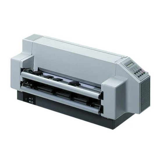
- Page 1 User ' s Manual High Speed Fanfold Printer High Speed Fanfold Printer with Cutter...
- Page 2 The contents of this manual are subject to change without notice. Copyright © by PSi Matrix GmbH. All rights strictly reserved. Reproduction or issue to third parties in any form is not permitted without written...
-
Page 3: Safety Regulations
Safety Regulations The printers PP 407 (High Speed Fanfold Printer) and the PP 408 (High Speed Fanfold Printer with Cutter) fulfils the safety regulations according to EN 60950-1, UL 60950-1 and CAN/CSA 22.2/No. 60950-1 for Information Technology Equipment. The mains cable must be connected to a ground protected wall-socket. The indicated voltage of the printer needs to agree with the local voltage. - Page 4 We certify that the equipment at issue, S Printer PP 407 (High Speed Fanfold Printer) and S Printer PP 408 (High Speed Fanfold Printer with Cutter) corresponds to the law regulations ruling electromagnetic compatibility of appliances (2004/108/EC) and, therefore, fulfils the requirements for conformity marking with the CE-sign.
- Page 5 Safety Regulations Operating Environment Avoid installing the printer where it is exposed to moisture or heat (eg. direct sun light). Temperature: + 10°C to + 35°C (+50°F to +95°F) Humidity: 20% to 80% Slots and openings in the printer's housing are provided for ventilation. Always ensure that these openings are not obstructed.
-
Page 7: Table Of Contents
Table of Contents Preface ............XI About this Manual . - Page 8 Safety Regulations 1.14 Emulation Selection ................1-23 2. Printer Operation ..................2-1 Control Panel ..................2-1 Function Keys..................2-2 2.2.1 Short Description of Keys ..............2-2 in the printer operation state READY or BUSY ......2-2 in the printer operation state LOCAL ........... 2-2 2.2.2 Detail Description of Keys in the printer operation state READY or BUSY ..............
- Page 9 Power-related Problems ................ 4-2 Error Messages ..................4-2 4.2.1 Errors during Selftest ................ 4-2 4.2.2 Errors during Printing ............... 4-4 4.2.3 Technical Errors ................4-6 No Printout .................... 4-7 Operation-related Problems ..............4-8 Print-related Problems ................4-9 Paper Jam ................... 4-11 Ribbon or Carriage-related Problems ..........
- Page 10 Table of Contents A. Configuring the Printer ........A-1 What is Configuring .
- Page 11 Table of Contents Main Function INSTALLATION ....... . . A-17 Sub-Function INTERFACE .
- Page 12 Table of Contents System Interface Descriptions ......B-1 Appendix B 1. Serial Interface RS 232 C ........B-2 2.
-
Page 13: Preface
Preface About this Manual This manual is covering the two printers – High Speed Fanfold Printer – High Speed Fanfold Printer with Cutter The operation and functionality are nearly the same. In most illustrations, the High Speed Fanfold Printer with Cutter is used. In case there are differences in the handling you will find the note: High Speed Fanfold Printer High Speed Fanfold Printer with Cutter... -
Page 14: A. Configuring The Printer
Preface 3. Maintenance Shows how to clean the printer and how to replace the platen and the print head. 4. Trouble Shooting and Diagnostics Suggests how to identify and correct simple problems. 5. Technical Data All technical details or data about the printer can be found here. Appendix A. -
Page 16: Conventions Used In This Guide
Preface Conventions Used in this Guide The following conventions are used: Bold Headlines and important information. Contains special advice to facilitate handling. Note: Contains important information to prevent damage Caution: of the equipment. [ENTER] Key functions are always depicted in brackets or you will find the symbol of the key e.g Abbreviations and Acronyms Automatic Gap Control... -
Page 17: Getting Started
1. Getting Started Unpacking the High Speed Fanfold Printer Check each item against the check list detailed below. Contact your reseller immediately if any item is missing or damaged. The printer package should contain the following parts: – 24-Needle Printer (1) Ribbon Cassette (2) –... - Page 18 Getting Started 1.1.1 A First Look at the High Speed Fanfold Printer Before installing the printer, spend some time familiarizing yourself with the printer. – Power Cord Socket (6) S Top Cover (1) – Control Panel (7) S Ribbon Cassette (2) –...
-
Page 19: Unpacking The High Speed Fanfold Printer With Cutter
Getting Started 1.2 Unpacking the High Speed Fanfold Printer with Cutter Check each item against the check list detailed below. Contact your reseller immediately if any item is missing or damaged. The printer package should contain the following parts: – Ribbon Cassette (2) S 24-Needle Printer (1) S Top Cover (2) (separate packing - see Packing Note) Cutting Device (3) (separate packing - see Packing Note) -
Page 20: A First Look At The High Speed Fanfold Printer With Cutter
Getting Started 1.2.1 A First Look at the High Speed Fanfold Printer with Cutter Before installing the printer, spend some time familiarizing yourself with the printer. – Control Panel (7) S Top Cover (1) – PM serial, parallel, USB (8) S Cutting Device (2) –... -
Page 21: Mounting The Cutting Device
Getting Started 1.2.2 Mounting the Cutting Device (only for High Speed Fanfold Printer with Cutter) S Insert the pins (3) of the Cutting Device (2) into the mounting plate (4). S Swivel the Cutting Device (2) to the Printer (1) and push the support plates (5) onto the pins (6). -
Page 22: Site Consideration
Getting Started 1.3 Site Considerations Environment Conditions S Install the printer in an area away from any heat source, air conditioner or strong draught. S Avoid installing the printer in a dusty or humid environment. Work Location S Place the printer on the stand or a flat, solid level area such as a desk. S Slots and openings in the printer's housing are provided for ventilation;... -
Page 23: Transport Lock
Getting Started 1.4 Transport Lock In delivery condition a red shipping tab is visible under the top cover (1), which is attached with the transport locking clip (2). Lift up the top cover (1) and remove the transport locking clip (2) from the print head drive belt. -
Page 24: Installing The Personality Module
Getting Started Installing the Personality Module The printer functions only in combination with an installed interface module, called a Personality Module (PM). The illustration below shows the standard PM with a serial, parallel, and USB interface. To avoid damage due to electrostatic discharge, do not touch the pins or Note: components of the PM. -
Page 25: The Power Supply
Getting Started The Power Supply Mains Voltage In general, the main's voltage selection is determined at factory sites. Make sure that the specified voltage on the label (1) corresponds to your main's voltage: S The 230 V setting applies to the range of 180 to 264 V alternating current. Since an incorrect voltage selection can seriously damage the printer, Note: please pay special attention to the following. -
Page 26: Power On/Off Switch
Getting Started Power ON/OFF Switch The power ON/OFF switch (1) turns the printer's power supply ON or OFF. After switched ON the printer an internal self-test which checks the electronics, the print head carriage movement and the interface will be performed. At first the yellow LED on the Operator Panel is lighting up and the display shows TEST..0.1 (bootstrap). - Page 27 Getting Started Installing the Ribbon Cassette It is recommended to use only original ribbon puts out by our company. Using other ribbons will void your warranty. Never manually move the print head fully to the right-hand stop (you Caution: could change the way of the paper output). If the printer is busy (message BUSY 1 ELQ) always press before Note:...
- Page 28 Getting Started 5. Position the ribbon feed guide (7) between the print head (4) and the green plastic plate (8). Continuation next page. 1-12...
- Page 29 Getting Started 6. Fit the upper mounting pins (9) into the green mounting brackets (10) and gently move the cassette toward you until you hear a click on both sides. Swing the ribbon underneath the print head (4) until the lower mounting pins (11) also engage with a click on both sides.
-
Page 30: Replacing The Ribbon Cassette
Getting Started 1.8.1 Replacing the Ribbon Cassette The print head may be very hot immediately after printing! Caution: 1. Close the top cover and power on the Printer. After the display shows READY 1 ELQ, open the top cover. The print head (4) will move to the correct position, aligned with the cut-out in the paper guide plate (5) to facilitate the installation of the ribbon cassette. -
Page 31: Inserting Fanfold Paper
Getting Started Inserting Fanfold Paper The printer has two tractor cassettes (1) for fanfold paper. They are named TRACTOR LOWER and TRACTOR UPPER. The standard setting of the paper source is the TRACTOR LOWER cassette. Ensure that the printer is placed in the depression on the top of the stand (option). - Page 32 Getting Started Insert the paper as shown in the illustration; the top edge of the paper must be equal with the top of the tractors or maximum up to two transport holes above the tractors. The left perforation should be aligned with the centre mark (1) on the plastic plate (6).
-
Page 33: Selection Of Operator Panel Language
Getting Started 1.10 Selection of Operator Panel Language The printer control panel and LCD display menu is used for the next steps. It is possible to change the language in the printer menu from English to French or German. The following example shows how to change from English to German: Taste Anzeige Switch the printer on. -
Page 34: Paper Source Selection
Getting Started 1.11 Paper Source Selection The TRACTOR LOWER is the default paper source. Using the control panel to change to the TRACTOR UPPER is explained below: Display 1. Switch the printer on. (93) LOCAL 7 TRACTOR LOWER (95) 4. [\] 7 TRACTOR UPPER 7 TRACTOR UPPER 5. -
Page 35: Test Prints
Getting Started 1.12 Test Prints There are three test prints available. S PRINT TEST 1 shows a pattern of all printable characters. Use this to check if the printer operates correctly. S PRINT TEST 2 produces a standard letter (ECMA-132) which can be used for measuring the printer's throughput. - Page 36 Getting Started Eilzustellung Norddeutsche Farbwerke KG Herrn Dr. Grauert Große Elbstraße 64 2000 Hamburg 4 Org. III 5/37 4 43 22.04.75 17.04.75 Volkmann Vordruckgestaltung für den allgemeinen Schrift- verkehr, für das Bestell- und Rechnungswesen E i l t Sehr geehrter Herr Dr. Grauert, Sie können das Schreiben der Briefe, Bestellungen, Rechnungen usw.
-
Page 37: Print Test 1
Getting Started To start a print test: Switch the printer ON (display shows READY 1 ELQ). The following identifies the keys to press and the corresponding operator panel messages. Display (93) LOCAL (94) MACRO SELECT [\] -- [\] INSTALLATION 7 INTERFACE [[] -- [[] 7 SELF TEST 7 PRINT TEST 1... -
Page 38: Connection To A Computer
Getting Started 1.13 Connection to a Computer Parallel, Serial, or USB Interface. S Switch the printer and computer OFF. S Connect the interface cable coming from the computer to the printer's parallel (1), serial (2), or USB port (3). S The printer is set by default to SHARED (PARALLEL/RS232) interface with the following parameters: S 8 Kbyte buffer S 8 bit... -
Page 40: Emulation Selection
1.14 Emulation Selection The following emulations are included in the PM Ser/Par/USB: S EPSON LQ / ESC/P2 in Macro 1 S IBM Proprinter XL 24 in Macro 2 S IBM Proprinter XL 24 AGM in Macro 3 S EPSON LQ / ESC/P2 in Macro 4 The factory setting is the EPSON LQ/ESC/P2 emulation in Macro 1. -
Page 41: Printer Operation
Printer Operation 2.1 Control Panel The control panel S controls the set-up for communication with the host computer S controls various parameter settings S allows manual control of the paper handling S gives information about the printer's status. The 16-character Liquid Crystal Display (LCD) (51) indicates the current status of the printer. -
Page 42: Function Keys
Printer Operation 2.2 Function Keys The function keys of the operator panel are grouped into two rows. The function of a key depends on the printer operation state. Following operation states are possible: READY or BUSY S LOCAL 2.2.1 Short Description of Keys –... -
Page 43: Detail Description Of Keys In The Printer Operation State Ready Or Busy
Printer Operation After pressing one of the keys the menu mode is Note: activated. Now the keys of the top row can only be used as cursor keys to move within the menu tree (right [Y], left [Z], up [[] and down [\]). -
Page 44: S Top Row Keys
Printer Operation S Top Row Keys The Quick Macro Selection mode is entered when one of the top row keys , or is pressed. From the left to the right macro 1 to macro 4 will be selected. Pressing of key causes the printer to change in the STOP-mode and in the display appears the message MACRO 2. - Page 45 Printer Operation This parameter covers a range of - to + / of an inch (0.42 mm), where "-" is up the page and "+" is further down the page (see also the table in Appendix A Configuring the Printer for VERT.POS.ADJ.). The set up of VERT.POS.ADJ.
- Page 46 Printer Operation How to Use this Function Preprinted paper (e.g. bill of lading) has to be adjusted exactly. Following errors are possible: S the printed value is too high - the fanfold paper has to be moved a little bit higher. S the printed value is too low - the fanfold paper has to be moved a little bit lower.
-
Page 47: S Lower Row Keys
Printer Operation There are two possibilities for the displacement to become active: S If a positive displacement is set before starting the print job the printer will move the paper into the right position first and then start printing. S If the displacement is set during a print job, the printer prints the contents of the print buffer. -
Page 48: Menu Mode
Printer Operation START/STOP Key (93) turns off the STOP indicator makes the printer ready for operation either starts the printout or self-test functions when selected (see MENU mode) or causes the interface status to change to READY or BUSY (displayed) exits the MENU mode. -
Page 49: To Activate The Menu
Printer Operation 2.3.1 To Activate the Menu: Press (93) The printer is in the STOP mode, the display shows LOCAL Press (94) in the top row of the control panel. As soon as the menu mode has been activated, the keys in the top row can only be used as cursor keys to move within the menu tree (up, down, right, and left). -
Page 50: To Confirm Selection
Printer Operation 2.3.2 To Confirm Selection: ’ - press [ ]; the confirmed value is displayed with an asterisk ( ) in the last position as shown in the picture before. All cursor keys have an auto repeat function. Note: The new confirmed settings are only valid until the printer is powered off. -
Page 51: How To Save Settings
Printer Operation 2.3.3 How to Save Settings The settings selected and confirmed are only active until the printer is switched off. In order to prevent losing your new settings you can save them using the MAIN FUNCTION SAVE. Display (93) LOCAL (94) MACRO SELECT... -
Page 52: Quick Settings
Printer Operation 2.3.4 Quick Settings The keys (94) (to select a pre-configured macro), (95), (96), and (97) are shortcuts in the menu tree. These particular selections can be changed quickly without having to move through the entire menu (see fold out of structure diagram). -
Page 53: Maintenance
3. Maintenance Preferred Materials The following materials and cleaning lubricants are recommended for use in the maintenance procedure: Lint-free cloth Vacuum cleaner. Cleaning The user should clean the printer every six months or after 50,000 prints, whichever occurs first. If you experience paper feed problems, or if the print head carriage movement becomes affected, cleaning should be carried out more often. - Page 54 Maintenance PRINT TEST 3 CONFIGURATION 20111234 01001234 2100 NLSF TNA1 TNA2 TNA3 5.00 PGCNT C031 ISO 8859/1 C032 ISO 8859/15 C061 C034 ISO 8859/5 C062 IBM C035 ISO 8859/9 IBM SET 1 C071 EPSON SET 2 C100 CODE PAGES EE C063 IBM CODE PAGE EXT.
-
Page 55: Cleaning Procedure
Maintenance Cleaning Procedure 1. Power the printer ON and remove the top cover. 2. Remove the ribbon cassette. 3. Thoroughly brush and vacuum all accessible areas to remove any paper flock and dust. 4. Clean the platen's surface, the paper pressure rollers and the transport rollers using the platen cleaner. -
Page 56: User Replaceable Parts
Maintenance User Replaceable Parts Replacement of the Print Head The print head has an expected life time of approximately 350,000 pages (see Page Counter (PGCNT in PRINT TEST 3). Print Head Removal The print head may be very hot immediately after printing. Caution: 1. -
Page 57: S Print Head Installation
Maintenance Print Head Installation Ensure that the printer is switched OFF. For print head installation, the carriage should be aligned with the cut-out in the paper guide plate (same position as for removal procedure). 1. Hold the print head (1) in its mounting position and press it against its stop in direction of the platen. -
Page 58: Replacement Of The Platen
Maintenance 3.3.2 Replacement of the Platen The platen needs to be replaced after approximately 800,000 pages (see Page Counter (PGCNT) in PRINT TEST 3). Remove the Platen (1) 1. Switch the printer OFF. 2. Lift and remove the top cover. 3. -
Page 60: Install The Platen
Install the Platen Ensure that the printer is switched OFF. 1. Place platen (1) in the vacant space between print head and metal bar. 2. Move print head from its right hand position into the centre. 3. Fit the gear wheel end of the platen into the right hand side mounting. Be careful not to damage the gear wheel. -
Page 61: Trouble Shooting And Diagnostics
Trouble Shooting and Diagnostics How to Use This Section Find the category to which your problem belongs. The problem categories are: Power-related Problems Error Messages No Printout Operation-related Problems Print-related Problems Paper Jam Ribbon or Carriage-related Problems Diagrams of Error For example, if the print appears very light on the paper, look at Section Print- related Problems. -
Page 62: Power-Related Problems
Trouble Shooting and Diagnostics Power-related Problems Power indicator does not come On when power is switched On Check that the power cord and plug are securely fitted to the printer and to an electrical outlet. Ask for the power connector connections (and fuse, if fitted) to be verified. Ask for the building electrical supply to be verified. - Page 63 Trouble shooting and Diagnostics Display That means... Cause I/O OK EEPROM located on EEPROM the Control Unit not not installed addressable not correctly installed defective If all tests have been passed successfully the following message will be displayed: Display That means... Cause / Action READY 1 ELQ The Printer is OK...
-
Page 64: Errors During Printing
Trouble Shooting and Diagnostics 4.2.2 Errors during Printing During normal operation the following error messages may occur: Display That means... Cause / Action LOCAL Entered in the Press to continue. OFFLINE mode when pressed. The STOP indicator is lit. COVER OPEN Top cover is To continue close the cover opened when... - Page 65 Trouble shooting and Diagnostics Display That means... Cause / Action CUTTER ERROR Paper jam in the Open the Cutter Unit and Cutter repair the paper jam (refer to (only High Speed paragraph 4.6 Paper Jam). Fanfold Printer with Cutter) Cutter without any Cutter not connected function Connector loose...
-
Page 66: Technical Errors
Trouble Shooting and Diagnostics 4.2.3 Technical Errors Display That means... Cause / Action AGC ERROR AGC ADJUST Distance print head and procedure fault platen faulty Print head loose Platen incorrectly installed Ribbon not inserted Horizontal drive without function Platen got dirty HOR. -
Page 67: No Printout
Trouble shooting and Diagnostics No Printout Self-test printout does not start Make sure that you have closed the cover. Check if paper is loaded in the printer. Refer to section 1.12 Test Printout. Printing does not start Make sure that the READY or BUSY message is displayed. If there is a different message displayed please refer to the above error message table. -
Page 68: Operation-Related Problems
Trouble Shooting and Diagnostics Operation-related Problems Paper is not positioned at perforation for tear-off Select the correct form length using the Set-up feature. Reset top of form by performing a Parking function. Refer to Appendix A.4 Vertical Positioning Adjustment Paper tears or jams Examine the paper path;... -
Page 69: Print-Related Problems
Trouble shooting and Diagnostics Print-related Problems Print faint or of poor quality. Have you used the correct paper? See chapter 5 Technical Data which contains a full specification of the paper you can use. Replace the paper if it does not match with the specification. Make sure that the ribbon is stretched correctly. - Page 70 Trouble Shooting and Diagnostics If the printout or the character set is not ok, the following procedure can help to clear the situation. Action Result Check Select and start PRINT Print not OK? PAPER SOURCE TEST 1 selection incorrect Ribbon worn or not installed Print head worn Stop SELF TEST and...
-
Page 71: Paper Jam
Trouble shooting and Diagnostics Paper Jam For the following steps stand in front of the printer, facing the tractor cassettes. Lift and remove the top cover. Grasp the cutter housing (1) (only for High Speed Fanfold Printer with Cutter) on both sides. Press down the green knobs (2) on the handles using your thumbs and swing the cutter to the rear. - Page 72 Trouble Shooting and Diagnostics In the following descriptions of paper jam recovery it is assumed that you stand in front of the printer, facing the tractor cassettes. The metal bar going through the paper guide plate above the platen is the so- called "D-shaft"...
-
Page 73: Ribbon Or Carriage-Related Problems
Trouble shooting and Diagnostics Ribbon or Carriage-related Problems Ribbon Problems Make sure that the ribbon is: Stretched correctly Not worn thin or dry Not torn or damaged in any other way Not jammed Carriage does not move smoothly Examine the paper path. Remove any obstructions. Check that all packing material is removed. -
Page 74: Diagrams Of Errors
Trouble Shooting and Diagnostics 4.9 Diagrams of Errors 4.9.1 PAPER JAM TRF (fanfold paper jam) DO NOT turn the printer off for paper jam recovery in order not to lose any Note: data. 4-14... -
Page 75: No Printout / No Printing
Trouble shooting and Diagnostics 4.9.2 NO PRINTOUT / NO PRINTING See also paragraph 4.3 Note: 4-15... -
Page 76: Print Faint Or Of Poor Quality
Trouble Shooting and Diagnostics 4.9.3 PRINT FAINT OR OF POOR QUALITY start PRINT TEST call your service >--- -- start adjust start PRINT TEST 3 *) callyour serv > -------1 continue printing *) see and Appendix Menu Structure A Gonfiguration of the Printer. 4-16... -
Page 77: Technical Data
5. Technical Data The following technical data refers to the Personality Module PM SER/PAR/USB. High Speed Fanfold High Speed Fanfold Printer Printer with Cutter Print Head Serial Impact Dot Matrix SIDM Technology Technology Paper Path Flat bed technology Print Head 24 needles, needle diameter 0.25 mm (0.01 inch), lifetime approximately 350,000 pages (standard DIN letter). - Page 78 Technical Data High Speed Fanfold High Speed Fanfold Printer Printer with Cutter Macros Up to four printer configurations selectable via Operator Panel or Software. ® Emulations ProPrinter XL24 (AGM) ® EPSON LQ 2550/1060 / ESC/P2 Print Speed (at 10 cpi) Draft Quality 700 cps Near Letter Quality...
- Page 79 Technical Data High Speed Fanfold High Speed Fanfold Printer Printer with Cutter Character Sets Code Pages EE: 437 GK, 851 GK, 928 GK, 855 CYRI, 852, 866, 869, Kamenicky, ISO Latin 2, Mazovia, 437 HUN, 852 SEE, 866 LAT, WIN LAT 2. Code Pages EE2: 771, 773, 774, 775, Baltic RIM 1125 Ukraine (866 U), 1251 Win Cyrillic.
- Page 80 Technical Data High Speed Fanfold High Speed Fanfold Printer Printer with Cutter Copies 1 original + 5 copies (max. total form thickness 0.5 mm [0.02 inch] ). ® Interface Parallel IEEE 1284 / Centronics compatible Serial RS-232C/V.24 USB 2.0 compatible Buffer Up to 160 Kbyte in selectable sizes.
- Page 81 Technical Data High Speed Fanfold High Speed Fanfold Printer Printer with Cutter Relative Humidity operating 20% up to 80% storage 5% up to 85% Noise Level 55 dB(A) (operating) acc. to ISO 7779 MTBF 10,000 h at 30% duty cycle Agency Approvals Acc.
- Page 82 Technical Data High Speed Fanfold High Speed Fanfold Printer Printer with Cutter Option for Printer Stand Stacker Option Stacking system for orderly stacking of 2,000 pages fanfold paper. width 460 mm; 18.1 inch depth 320 mm; 12.6 inch height 450 mm; 17.8 inch Cut Sheet Tray Output tray for max.
- Page 83 Technical Data High Speed Fanfold High Speed Fanfold Printer Printer with Cutter Paper Handling Paper Paths Flatbed technology. Paper Input Two independent, easy to plug-in tractor cassettes for (Tractor Cassettes) fanfold paper, with zero tear off; push tractor with park position width 520 mm;...
-
Page 84: Label Processing
Technical Data High Speed Fanfold High Speed Fanfold Printer Printer with Cutter Paper Weight for both printer Minimum Maximum 1-ply 60 g/m ; 16 lb/ream 90 g/m ; 24 lb/ream multiple (per sheet) 40 g/m ; 10 lb/ream 60 g/m ;... - Page 85 Technical Data Labels Processing During the processing of adhesive labels on both printers the following must be considered:: The surface of the labels must be absorbent, in order to take up the ribbon liquid. Labels may not separate during printing from the carrier paper. Turn over the corners of the labels are not permissible, since the label under the shield of the print head can stick.
-
Page 87: What Is Configuring
Configuring the Printer Appendix A What is Configuring This chapter describes how to use the menu settings via the operator panel to set up or configure the printer and computer system in a way that they can communicate correctly with each other. Communication between the two requires that both the computer operating system and the printer have the same communication settings or features. - Page 88 Appendix A Configuring the printer Display 1. Switch the printer ON READY 1 ELQ (93) LOCAL (94) MACRO SELECT 4. [ PRINT OUT 5. [ PRINT OUT ’ 6. [ PRINT OUT ’ (93) PRINT OUT After feeding paper from the defined paper source, the printer starts to print. When printing is completed, the following message will be displayed: PRINT OUT (93)
-
Page 89: Standard Configuration
Appendix A Configuring the printer A.2 Standard Configuration The standard configuration is reflected in the following printout provided that no parameters have been changed. A.2.1 for the High Speed Fanfold Printer PRINT OUT VERSION 208xxxxx INTERFACE ADJUSTMENT BUFFER 8 KBYTE AGC POSITION WORD LENGTH 8 BIT... -
Page 90: For The High Speed Fanfold Printer With Cutter
Appendix A Configuring the printer A.2.2 for the High Speed Printer with Cutter PRINT OUT VERSION 202xxxxx INTERFACE ADJUSTMENT BUFFER 8 KBYTE AGC POSITION WORD LENGTH 8 BIT PLATEN GAP I/F TYPE SHARED PAPER-IN ADJ. BAUD-RATE 9600 BPS CUT. V-POS LO. PARITY BIT EVEN CUT. -
Page 91: Explanation Of The Printout On The Previous Page
Appendix A Configuring the printer A.3 Explanation of the printout on the previous page The heading PRINT OUT gives information about the VERSION of the printer's firmware. The next two headings are followed by two columns of standard settings: INTERFACE - for communication between the computer operating system and the printer it is necessary to have the same communication settings or features. -
Page 92: Explanation Of Individual Menu Items
Appendix A Configuring the printer Explanation of Individual Menu Items Main Functions The following main functions are available: MACRO SELECT To select one of the four macros which can be used for quickly changing the printer settings for different applications. For example: Application A need's fanfold paper cut into single sheets with a top margin of one, application B processes fanfold paper in a batch with a top margin of six. -
Page 93: Sprint Out
Appendix A Configuring the printer PRINT OUT This function initiates a printout of the parameter settings and macro definitions. This printout is helpful for future reference and when macros need to be changed. To actually start the print operation it is necessary to leave the STOP mode (by pressing the key - see also Chapter A.1). -
Page 94: Sprint Quality
Appendix A Configuring the printer PRINT QUALITY The Print Quality is split up into three parts: FONT QUALITY Three different font quality levels can be selected: Draft quality (font “Data”) Near letter quality (NLQ will be displayed with the font name) Letter quality (LQ displayed with the font name). -
Page 95: Spitch
Appendix A Configuring the printer Pitch Indicates the number of characters printed per inch (10, 12, 15, 17, 18, 20 or proportional). Any pitch setting can be combined with any available font. In some cases this may lead to a conflict with font designs. The pitch setting is, therefore, a matter of personal taste. -
Page 96: Vert.pos.adj
Appendix A Configuring the printer Vertical Positioning Adjustment (VERT.POS.ADJ.) This function changes the vertical position in the current macro for the two different paper paths TRACT.L. V-POS and TRACT.U. V-POS exactly position the printout in relation to the top edge of the form in use. It is meant to be a corrective parameter to meet variations in paper size and preprinted material. -
Page 97: S Right Margin
Appendix A Configuring the printer The RIGHT MARGIN is set to print position 80, 132 or 136, always measured from the position of the first possible, not actual, left margin setting. The left margin setting is influenced by the physical setting of the left tractor. The above specifications are only correct if the tractors are in the original positions, i.e. -
Page 98: Sperforation Skip
Appendix A Configuring the printer The BOTTOM MARGIN indicates the last print line. Going beyond this margin automatically initiates a form feed. The bottom margin is always set in steps / ". The bottom margin can be set to a maximum of / ". -
Page 99: Spaper Exit
Appendix A Configuring the printer Paper Exit (only for High Speed Fanfold Printer with Cutter) It is possible to choose between BATCH (to leave the printer at the rear) and STACKER (at the top) via the point PATH. If BATCH is selected, the paper keeps its continuous form and leaves the printer at the rear. -
Page 100: Semulation
Appendix A Configuring the printer Emulation The emulation determines the set of commands available for the printer (see Appendix D and E). You can activate the following emulations: EPSON LQ IBM PROPR. IBM PROPR.AGM The selected Emulation will also be stored in the actual macro. With a Note: change of the macro (e.g. -
Page 101: S $$ Commands
Appendix A Configuring the printer $$ Commands This function causes $$ either to be printed as $$ or to activate ESC commands within an application. If this function is set to YES the characters are interpreted by the printer in the following way: $$ as ESC [ $$/ as ESC. - Page 102 Appendix A Configuring the printer The setting TEAR - OFF 10 S causes the paper to move into the tear off position if no new printing data have been received within 10 seconds. This setting supports applications lacking a programmed form feed after the completion of a print job.
-
Page 103: Main Function Installation
Appendix A Configuring the printer Main-Function INSTALLATION Sub-Function INTERFACE BUFFER Buffer size in Kbyte. The maximum size is 176 Kbyte. WORD LENGTH Length of the data to be transferred; values are 7 or 8 bit. I/F TYPE (Interface Type) the following types are available: PARALLEL SERIAL SHARED... -
Page 104: Sbaud Rate
Appendix A Configuring the printer BAUD RATE (only indicated if the serial interface is selected) Controls the speed of data transfer. The possible transfer rates are: 600, 1200, 2400, 4800, 9600 or 19200 bps. PARITY BIT (only indicated if the serial interface is selected) The data transfer will be checked by an even or odd parity bit. -
Page 105: Sub-Function Adjustment
Appendix A Configuring the printer Sub-Function ADJUSTMENT AGC Position AGC (Automatic Gap Control) is an integral part of the paper handling capabilities of the printer. It is an automatic adjustment function which ensures an optimal print quality when using paper of various thicknesses. The gap adjustment will automatically take place whenever paper is inserted after the paper source has been changed... -
Page 106: Splaten Gap
Appendix A Configuring the printer Platen Gap This adjustment is to be seen as a correctional offset to the platen gap set by the AGC (Automatic Gap Control) function or a PCC (Program- mable Copy Control) command. It effects all paper paths. The offset is within the range of -3 to +4. -
Page 107: Scut. V-Pos Lo. / Cut. V-Pos Up
Appendix A Configuring the printer CUT. V-POS LO. / CUT. V-POS UP. (Vertical Positioning for Cutting Device for the High Speed Fanfold Printer with Cutter or for the tear off edge on the High Speed Fanfold Printer) This can be set differently for each paper source (lower and upper tractor) and is meant to be a corrective parameter to meet variations in paper size and pre-printed material. -
Page 108: Slanguage
Appendix A Configuring the printer Special Sub-Items under INSTALLATION Language The operator panel may display its messages in three languages. Select one out of the following: ENGLISH, DEUTSCH, FRANCAIS. RESTORE SET UP With this function all settings of the last SAVE procedure will be restored. RECALL FACTORY All standard settings of the firmware will be restored. -
Page 109: Sself Test
Appendix A Configuring the printer SELF TEST PRINT TEST 1 (see Chapter 1.12 Test Prints) PRINT TEST 2 (see Chapter 1.12 Test Prints) PRINT TEST 3 gives information about technical releases and is intended for service purposes only. Among other information, the page counter identifies the number of pages printed. -
Page 110: Configuration Menu
Appendix A Configuring the printer Configuration Menu High Speed Fanfold Printer and High Speed Fanfold Printer with Cutter 1. Press the - key first. MACRO SELECT MACRO 1 CHANGE MACRO MACRO 2 TRACT.L. V-POS INSTALLATION MACRO 3 TRACT.U. V-POS SAVE MACRO 4 PRINT OUT EPSON EXT. -
Page 111: Appendix B System Interface Descriptions
Appendix B System Interface Description Appendix B System Interface Description The Standard Personality Module (PM) offers three system interfaces: serial interface with RS-232C support ® Parallel IEEE 1284 / Centronics compatible USB 2.0 compatible. The interfaces can be operated in different modes: parallel interface active serial interface active parallel and serial RS-232C interfaces in a shared mode... -
Page 113: Serial Interface Rs-232C
Appendix B System Interface Description Serial Interface RS-232C The serial interface has one asynchronous V24 RS232C . Technical Character: The following parameters can be modified in SET-UP: BAUD RATE: 2400, 4800, 9600, 19200 (bit/s) BITS/CHARACTER: 7 or 8 bits STOP BITS: In receive mode the printer accepts 1, or 2 stop bits. -
Page 114: Parallel Interface
Appendix B System Interface Description Parallel Interface The parallel interface according to IEEE 1284 standard, support SPP, nibble, byte protocol. Technical Character: ® Compatibility: Centronics Logic circuits: Data format: 7 or 8 bits Logics level: 0 - 5 V Connector: 36 pins All the input and output signals were connected to a 5V voltage by a 2.2k ohm resistance... -
Page 115: Additional Information
Appendix B System Interface Description Additional Information After Power-ON DTR and RTS are activated and the printer is ready to receive data. XOFF is sent, when the interface buffer has only space left for 256 more charac- ters. XOFF is sent again, at a level of 128 characters buffer space. Further incoming data will be stored until the interface buffer is full. -
Page 116: Usb Interface
Appendix B System Interface Description If the serial interface starts to receive data while the parallel interface is active, it is possible to receive 256 bytes of serial data. Any additional serial data will be lost. When the interface buffer is completely empty of serial data, and no new data has been received by the serial interface for more than 10 seconds, both interfaces are available for data transfer again. -
Page 117: Appendix C Character Set Table
Appendix C Character Set Tables Appendix C Character Set Tables Code Page ISO 8859-1 ° À Ð à ð ¡ ± Á Ñ á ñ " ¢ ² Â Ò â ò £ ³ Ã Ó ã ó ¤ Ä Ô... - Page 118 Appendix C Character Set Tables Code Page ISO 8859-15 ° À Ð à ð ¡ ± Á Ñ á ñ " ¢ ² Â Ò â ò £ ³ Ã Ó ã ó Ž Ä Ô ä ô ¥ µ Å...
- Page 119 Appendix C Character Set Tables Code Page ISO 8859-5 " ...
- Page 120 Appendix C Character Set Tables Code Page ISO 8859-9 ° À Ǧ à ğ ¡ ± Á Ñ á ñ ¢ ² Â Ò â ò £ ³ Ã Ó ã ó ¤ Ä Ô ä ô ¥ µ Å Õ...
- Page 121 Appendix C Character Set Tables Code Page IBM All Character Set ∅ ▸ SP 0 @ P ╨ α ░ └ Ç É á ≡ 1 ☺ ◂ ▒ ┴ ╤ β ü æ í ± 2 ☻ ↕ ʺ ▓...
- Page 122 Appendix C Character Set Tables Code Page IBM Set 1 National Version = USA α ░ ╨ á └ ≡ β ▒ ┴ ╤ í ± ʺ Γ ▓ ┬ ╥ ó ≥ ├ ╙ π ú │ ≤ Σ ┤...
- Page 123 Appendix C Character Set Tables National Version IBM Set 1 Character Code (Hex) 23 24 40 5B 5C 5D 5E 60 7B 7C 7D 7E 1: USA 2: FRANCE à ° ç § é ù è 3: GERMANY § Ä Ö...
- Page 124 Appendix C Character Set Tables Code Page IBM Set 2 α ░ ╨ Ç É á └ ≡ ▒ ┴ ╤ β ± ü æ í ʺ Γ ▓ ┬ ╥ é Æ ó ≥ ♥ π ├ ╙ â ô...
- Page 125 Appendix C Character Set Tables National Version IBM Set 2 Character Code (Hex) ¢ ¥ 1: USA à ° ç § é ù è ¢ ¥ 2: FRANCE § Ä Ö Ü ä ö ü ß ¢ ¥ 3: GERMANY £...
- Page 126 Appendix C Character Set Tables IBM Code Pages Code Page Countries 5.1: Code Page 437 5.2 : Code Page 850 Germany, UK, Denmark, Sweden, Italy, Spain, Japan, Latin Am., Turkey 5.3 : Code Page 858 Germany, UK, Denmark, Sweden, Italy, Spain, Japan, Latin Am, Turkey;...
- Page 127 Appendix C Character Set Tables C.10 IBM Code Page 437 USA, ASCII, and Graphics ∅ α ░ ╨ ▸ Ç É á └ ≡ ☺ β ▒ ┴ ╤ ◂ ü æ í ± ☻ ↕ ʺ ▓ ┬ ╥ Γ...
- Page 128 Appendix C Character Set Tables C.11 IBM Code Page 850 Greek (437) and ISO 8859-1 ∅ ░ ▸ └ Ç É á ð Ó ☺ β ▒ ┴ ◂ ü æ í Ð ± ☻ ↕ ʺ ▓ ┬ é Æ...
- Page 129 Appendix C Character Set Tables Latin 1 and i Sign C.12 IBM Code Page 858 ∅ ░ ▸ Ç É á └ ð Ó ☺ ◂ β ▒ ┴ Ð ü æ í ± ☻ ↕ ʺ ▓ ┬ Ê é...
- Page 130 Appendix C Character Set Tables C.13 IBM Code Page 860 Portugal ∅ ░ ╨ α ▸ └ ≡ Ç É á ☺ β ▒ ┴ ╤ ◂ ü À í ± ☻ ↕ ʺ ▓ ┬ ╥ Γ ≥ é È...
- Page 131 Appendix C Character Set Tables C.14 IBM Code Page 863 Canada, French ∅ ░ ╨ α ▸ └ ≡ Ç É ☺ β ▒ ┴ ╤ ◂ ü È ± ☻ ↕ ʺ Γ ▓ ┬ ╥ é Ê ó ≥...
- Page 132 Appendix C Character Set Tables C.15 IBM Code Page 865 Norway 9 A B C D E ∅ ░ ╨ α ▸ └ ≡ Ç É á ☺ β ▒ ┴ ╤ ◂ ü æ í ± ☻ ↕ ʺ ▓...
- Page 133 Appendix C Character Set Tables C.16 IBM Code Page 857 Turkey ░ á └ Ó ▒ ┴ í ß ± ▓ ┬ " ò Ê Ô ├ ú │ Ë Ò ¾ ┤ ñ È õ ¶ ┼ Ñ Á Õ...
- Page 134 Appendix C Character Set Tables C.17 EPSON Extended Graphics Code Page ░ ╨ α └ ≡ Ç É á β ▒ ┴ ╤ ü æ í ± ʺ ▓ ┬ ╥ Γ ≥ é Æ ó ├ ╙ π │ ≤...
- Page 135 Appendix C Character Set Tables C.18 National Version EPSON Extended graphics Code Page Character Code (Hex) 1: USA 2: FRANCE à ° ç § é ù è 3: GERMANY § Ä Ö Ü ä ö ü ß 4: UK £ 5: DENMARK Æ...
- Page 136 Appendix C Character Set Tables C.19 EPSON Italic Code Page " " & & < < > > This Code Page is selected by the command ESC t. C-20...
- Page 137 Appendix C Character Set Tables C.20 National Version EPSON Italic Code Page (part 1) Character Code (Hex) 1: USA 2: FRANCE à ° ç § é ù è 3: GERMANY § Ä Ö Ü ä ö ü ß 4: UK £...
- Page 138 Appendix C Character Set Tables C.21 National Version EPSON Italic Code Page (part 2) Character Code (Hex) 1: USA 2: FRANCE à ° ç § é ù è 3: GERMANY § Ä Ö Ü ä ö ü ß 4: UK £...
- Page 139 Appendix C Character Set Tables Code Pages for the Eastern European Countries (EE) C.22 Code Page 437 Greek Α Ρ ι ░ ╨ ω ʼ Ω └ Β Σ κ ἀ ▒ ┴ ╤ ± ʺ Γ Τ λ ἐ ▓...
- Page 140 Appendix C Character Set Tables C.23 Code Page 851 Greek ϊ Τ ζ ░ Ί └ Ç Υ η ▒ ┴ ü ± ʺ ὀ Φ θ υ ▓ ┬ ʼ Ο é ὐ Χ ι ϕ ├ │ â ô...
- Page 141 Appendix C Character Set Tables C.24 Code Page 928 Greek ̊ Π π Ç É ΐ ΰ Α Ρ α ρ ü æ ‛ ± ʺ Β β ς é Æ ’ ² Γ Σ γ σ â ô £ ³...
- Page 142 Appendix C Character Set Tables C.25 Code Page 855 Cyril – " " ...
- Page 143 Appendix C Character Set Tables C.26 Code Page 866 Russia ░ ╨ А Р а └ р Ё ▒ ┴ ╤ Б С б с ё ʺ ▓ ┬ ╥ В Т в т Є ├ ╙ Г У г │...
- Page 144 Appendix C Character Set Tables C.27 Code Page 869 Greek ░ Ί ϊ └ Τ ζ − ▒ ┴ Ї ΐ Υ η ± ʺ ▓ ┬ ʼ Ο ὀ Φ θ υ ├ ὐ │ Χ ι ϕ ┤ Α...
- Page 145 Appendix C Character Set Tables C.28 Code Page 852 Multilingual Latin 2 ░ Ç É á └ ð Ó ▒ ┴ ü Ĺ í Ð ß ̋ ʺ ▓ ┬ é Ľ ó Ď ô ̨ ├ â ô ú │...
- Page 146 Appendix C Character Set Tables C.29 Code Page KAMENICKY ░ ╨ Č É á └ α ≡ ▒ ┴ ╤ ü ž í β ± ʺ ▓ ┬ ╥ é Ž ó Γ ≥ ├ ╙ ď ô ú │ ∏...
- Page 147 Appendix C Character Set Tables C.30 Code Page ISO LATIN 2 ̊ Ŕ Ð ŕ ð Ą ą Á Ń á ń ʺ ̆ ˛ Â Ň â ň Ł ł Ă Ó ă ó ¤ Ä Ô ä ô Ľ...
- Page 148 Appendix C Character Set Tables C.31 Code Page MAZOVIA ░ ╨ Ç Ę Ź └ α ≡ ▒ ┴ ╤ ü ę Ż β ± ʺ ▓ ┬ ╥ é ł ó Γ ≥ ├ ╙ â ô Ó │ π...
- Page 149 Appendix C Character Set Tables C.32 Code Page 437 HUN ░ ╨ Ç É á └ α ≡ ▒ ┴ ╤ ü æ í β ± ʺ ▓ ┬ ╥ é Æ ó Γ ≥ ├ ╙ â ő ú │...
- Page 150 Appendix C Character Set Tables C.33 Code Page 852 SEE ░ Ž ž Ç É á └ ð Ó ▒ ┴ ü Ľ í Ð ß ̋ ʺ ▓ ┬ é ľ ó Ď Ô ̨ ├ â ô ú │...
- Page 151 Appendix C Character Set Tables C.34 Code Page 866 LAT ∅ ░ ▸ ‛ А а └ Š р Ē ☺ ▒ ┴ ╤ ◂ Б б с ē ☻ ▓ ┬ ↕ " В в č т Ģ ♥ ⌈...
- Page 152 Appendix C Character Set Tables C.35 Code Page WIN LAT2 ∅ ▸ ̊ Ŕ Ð ŕ ð ☺ ◂ ̆ ± Á Ń á ń ☻ ʺ ↕ ́ ̆ ˛ Â Ň â ň ♥ ‼ ‟ Ł ł Ă...
- Page 153 Appendix C Character Set Tables Code Pages for the Eastern European Countries (EE2) C.36 Code Page 771 Lithuanian and Russian ∅ ░ ╨ ▸ А а └ р Ę ☺ ▒ ┴ ╤ ◂ Б б с ę ☻ ▓ ┬...
- Page 154 Appendix C Character Set Tables C.37 Code Page 773 Latin 7 (Baltic old standard) ∅ ░ ▸ Ċ É Ā └ ̊ Ó Ę ☺ ▒ ┴ ╤ ◂ ü æ Ī ß ę ☻ ▓ ┬ ↕ " é Æ...
- Page 155 Appendix C Character Set Tables C.38 Code Page 774 Lithuanian = IBM 1118 ∅ ą α ░ ▸ Ç É á └ ≡ ☺ ▒ ┴ č β ◂ ± ü æ í ☻ ę Γ ▓ ┬ ↕ " é...
- Page 156 Appendix C Character Set Tables C.39 Code Page 775 (Baltic Rim) ∅ ░ ▸ Ċ É Ā └ ą Ó ☺ ▒ ┴ ◂ ü æ Ī č β ± ☻ ▓ ┬ ↕ " é Æ ó ę Ō “...
- Page 157 Appendix C Character Set Tables C.40 Code Page BALTIC RIM ∅ ▸ ° Ą Š ą š ☺ ◂ ˎ ± Į Ń į ń ” ☻ ↕ " ˊ ¢ ² Ā Ņ ā ņ ♥ ‼ £ ³ Ć...
- Page 158 Appendix C Character Set Tables C.41 Code Page 1251 Win Cyrillic ° А Р а р ў ± Б С б с ʺ ӯ І В Т в т Ј і Г У г у ¤ г Д Ф д ф...
- Page 159 Appendix C Character Set Tables C.42 Code Page 1125 / 866 Ukrainian ░ ╨ ́ а └ р Ё ▒ ┴ ╤ б с ё ʺ ▓ ┬ ╥ в т Г ├ ╙ г │ у г ┤ ╘ д...
- Page 160 Appendix C Character Set Tables C.43 Code Page OCR-A 0 NUL DLE SP ┌ │ SOH DC1 ʺ STX DC2 ETX DC3 EOT DC4 5 ENQ NAK ACK SYN & ̓ BEL ETB BS CAN LF SUB VT ESC ¬ <...
- Page 161 IBM ProPrinter Quick Reference Appendix D This appendix contains basic information on the IBM ProPrinter 4207, 4208 XL 24 Emulation commands supported in four Printer types: Fanfold Printer Multi-purpose Printer High Speed Fanfold Printer High Speed Fanfold Printer with Cutter Some commands or parameters may be different for a specific Printer.
-
Page 162: Appendix D Ibm Proprinter 4207, 4208 Xl 24 Quick Reference
Appendix D IBM ProPrinter 4207, 4208 XL 24 Quick Reference Characters used in control functions appear in monospaced type. Table 1 explains some of the conventions used. A pair of numbers separated by a slash ( / ) character indicates Column/Row notation. This notation refers to the location of a character in a standard code table, such as ASCII. - Page 163 Appendix D IBM ProPrinter 4207, 4208 XL 24 Quick Reference Table 2: Control Codes Column/Row Mnemonic Function Null Backspace Horizontal Tab Line Feed Vertical Tab Form Feed Carriage Return Double Width Printing By Line Condensed Printing (17.1 cpi) Select Printer ½...
- Page 164 Appendix D IBM ProPrinter 4207, 4208 XL 24 Quick Reference Table 3: Vertical Form Handling Escape Sequence Mnemonic Function ESC 0 Set Line Space to " ESC 1 Set Line Space to " ESC 2 Start Variable Line Space ESC 4 Set Top of Form ESC 5 P1 Carriage Return Function...
- Page 165 Appendix D IBM ProPrinter 4207, 4208 XL 24 Quick Reference Table 3 (Cont.): Vertical Form Handling Escape Sequence Mnemonic Function ESC ] Reverse Line Feed ESC ] > s Insert Form Native Command ESC [ > P1 ; P2 ; P3 ; P4 s SPSIF Select Paper Source and Insert Native Command...
- Page 166 Appendix D IBM ProPrinter 4207, 4208 XL 24 Quick Reference Table 3 (Cont.): Vertical Form Handling High Speed Fanfold Printer with Cutter...
- Page 167 Appendix D IBM ProPrinter 4207, 4208 XL 24 Quick Reference Table 3 (Cont.): Vertical Form Handling Escape Sequence Mnemonic Function ESC [ ; ; P3 s Paper Exit: Native Command P3 = 0 : Paper Exit Stacker ***) P3 = 1 : Paper Exit Front Side **) (confirmed by Start/Stop key) P3 = 2 :...
- Page 168 Appendix D IBM ProPrinter 4207, 4208 XL 24 Quick Reference Table 4 (Cont.): Horizontal Form Handling and Printing Modes Escape Sequence Function ESC : Select Elite (12 cpi) ESC - P1 Cancel / Select Underline P1 = 0/0 cancel Underline Printing P1 = 0/1 set Underline Printing ESC _ P1 Cancel / Select Overline Printing P1 = 0/0 cancel...
- Page 169 Appendix D IBM ProPrinter 4207, 4208 XL 24 Quick Reference Table 4: Horizontal Form Handling and Printing Modes Escape Sequence Function ESC E Select Emphasized Printing (bold) ESC F Cancel Emphasized Printing (bold) ESC G Select Double Strike Printing (bold) ESC H Cancel Double Strike Printing ESC I P1...
- Page 170 Appendix D IBM ProPrinter 4207, 4208 XL 24 Quick Reference Table 4 (Cont.): Horizontal Form Handling and Printing Modes Escape Sequence Mnemonic Function ESC W P1 Cancel / Select Double Width P1 = 0/0 or 0 : cancel Double Width P1 = 0/1 or 1 : select Double Width ESC X P1 P2 Set Left and Right Margins P1...
- Page 171 Appendix D IBM ProPrinter 4207, 4208 XL 24 Quick Reference Table 4 (Cont.): Horizontal Form Handling and Printing Modes Escape Sequence Mnemonic Function ESC [ P1 ; P2 x Select Font and Character Pitch Native Command (parameter P1 or P2 may be skipped, see following alternative command sequences) ESC [ P1 x P1 selects the font...
- Page 172 Appendix D IBM ProPrinter 4207, 4208 XL 24 Quick Reference Escape Sequence Mnemonic Function ESC 6 Select Character Set 2 ESC 7 Select Character Set 1 ESC \ P1 P2 Print from All Character Set Number of codes = (P1 + P2 * 256) (Pn = 0/0...F/F) ESC ^ P1 Print Single Character from All Character Set P1 = Number of Char.
- Page 174 Appendix D IBM ProPrinter 4207, 4208 XL 24 Quick Reference Table 6: Graphics Modes Escape Sequence Mnemonic Function ESC 3 P1 Set Line Space to " ( / ") lpi (non AGM), lpi (AGM) (P1 = 0/1...F/F) ESC J P1 Perform "...
- Page 175 Appendix D IBM ProPrinter 4207, 4208 XL 24 Quick Reference Table 6 (Cont.): Graphics Modes Escape Sequence Mnemonic Function ESC [ g P1 P2 P3 v1 . . . vn Select Various Graphics Modes (IBM) P1 + P2 * 256 = number of data bytes + 1 (P1,P2 = 0/0...F/F) v1 ..
- Page 176 Appendix D IBM ProPrinter 4207, 4208 XL 24 Quick Reference Table 7: Further Control Sequences, supported by IBM Emulation Mode (Native Commands) Escape Sequence Mnemonic Function ESC [ Control String Introducer (CSI) for 'ESC [' Control String Introducer (CSI) for 'ESC' ESC * P1 P2 P3 v1 .
- Page 177 Appendix D IBM ProPrinter 4207, 4208 XL 24 Quick Reference Table 7 (Cont.): Further Control Sequences, supported by IBM Emulation Mode (Native Commands) Escape Sequence Mnemonic Function ESC [ P1 ; P2 w SNVCT Set National Version and Code Table P1 = 1 - 15 national version Depending on selected character set (see Appendix C Char.
- Page 178 Appendix D IBM ProPrinter 4207, 4208 XL 24 Quick Reference Table 7 (Cont.): Further Control Sequences, supported by IBM Emulation Mode (Native Commands) Escape Sequence Mnemonic Function ESC [ P1 ; P2 SP r SM # Select Macro and Change Emulation P1 = 1: Macro 1 P1 = 2: Macro 2 P1 = 3: Macro 3...
- Page 179 Appendix D IBM ProPrinter 4207, 4208 XL 24 Quick Reference Table 7 (Cont.): Further Control Sequences, supported by IBM Emulation Mode (Native Commands) Escape Sequence Mnemonic Function ESC [ P1 a Set Horizontal Position Relative P1 = print column (P1 = 0...9999) ESC [ P1 b Repeat Character P1 = number of repetitions...
- Page 180 Appendix D IBM ProPrinter 4207, 4208 XL 24 Quick Reference Table 7 (Cont.): Further Control Sequences, supported by IBM Emulation Mode (Native Commands) Escape Sequence Mnemonic Function ESC [ P1 m Set Graphic Rendition P1 = 0: default - no rendition or rendition reset P1 = 1: bold...
- Page 181 Appendix D IBM ProPrinter 4207, 4208 XL 24 Quick Reference Table 7 (Cont.): Further Control Sequences, supported by IBM Emulation Mode (Native Commands) Escape Sequence Mnemonic Function ESC [ ; P2 ; P3 ; P4 ; P5 ; P6 ; P7 SP z BARCODE Programming Barcode Header Barcode typ...
- Page 182 Appendix D IBM ProPrinter 4207, 4208 XL 24 Quick Reference Hex Code Format Page Null Backspace Horizontal Tab Line Feed Vertical Tab Form Feed Carriage Return Select Double Width (one line) Select Condensed Printing (17.1 cpi) Select Printer Select Pica (10 cpi) Buffer Data Flow Control Cancel Double Width Cancel Buffer...
- Page 183 Appendix D IBM ProPrinter 4207, 4208 XL 24 Quick Reference Hex Code Format Page 1B 48 Cancel Double Strike 1B 4D Reverse Line Feed D-16 1B 4F Cancel Automatic Perforation Skip 1B 52 Restore Horizontal Tabs to Default 1B 54 Cancel Superscript/Subscript 1B 5D Reverse Line Feed...
- Page 184 Appendix D IBM ProPrinter 4207, 4208 XL 24 Quick Reference D-20...
- Page 186 Appendix D IBM ProPrinter 4207, 4208 XL 24 Quick Reference Hex Code Format Page AGC / PCC Procedure 1B 5B 3B P Set Code Table D-15 1B 5B 3B P 1B 5B 3B P 3B P 3B P 3B P 3B P Bar Code Header D-19...
- Page 187 Appendix D IBM ProPrinter 4207, 4208 XL 24 Quick Reference Hex - Decimal Conversion Table 224 240 225 241 226 242 227 243 228 244 229 245 230 246 231 247 232 248 233 249 234 250 235 251 236 252 237 253 238 254 239 255...
- Page 189 EPSON LQ 2550 and ESC/P2 Quick Reference Appendix E This appendix contains basic information on the EPSON LQ 2550 and ESC/P2 Printer Emulation commands supported in four Printer types: Fanfold Printer Multi-purpose Printer High Speed Fanfold Printer High Speed Fanfold Printer with Cutter Some commands or parameters may be different for a specific Printer.
- Page 190 Appendix E EPSON LQ 2550 and ESC/P2 Quick Reference Characters used in control functions appear in monospaced type. Table 1 explains some of the conventions used. A pair of numbers separated by a slash ( / ) character indicates Column/Row notation. This notation refers to the location of a character in a standard code table, such as ASCII.
- Page 191 Appendix E EPSON LQ 2550 and ESC/P2 Quick Reference Table 2: Control Codes Column/Row Mnemonic Function Null Backspace Horizontal Tab Line Feed Vertical Tab Form Feed Carriage Return Double Width Printing By Line Condensed Printing Select Printer ½ Select Pica (10 cpi) Deselect Printer Cancel Double Width Printing By Line Cancel Buffer...
- Page 192 Appendix E EPSON LQ 2550 and ESC/P2 Quick Reference Table 4: Vertical Form Handling Escape Sequence Mnemonic Function ESC 0 Set Line Space to " ESC 2 Set Line Space to " ESC 3 P1 Set Line Space to " (P1 = 0...255) ESC + P1 Set Line Space to "...
- Page 193 Appendix E EPSON LQ 2550 and ESC/P2 Quick Reference Table 5: Vertical Form Handling Escape Sequence Mnemonic Function ESC EM P1 Form Feed and ASF Control *) EM = 1/9 P1 = 0/1 or 1: ASF Bin 1 P1 = 0/2 or 2: ASF Bin 2 P1 = 0/3 or 3: ASF Bin 3 P1 = 8/2 or R: (5/2) eject sheet ESC [ >...
- Page 194 Appendix E EPSON LQ 2550 and ESC/P2 Quick Reference Table 4: Vertical Form Handling **) only Fanfold Printer, and Multi-purpose Printer ***) only High Speed Fanfold Printer and High Speed Fanfold Printer with Cutter...
- Page 195 Appendix E EPSON LQ 2550 and ESC/P2 Quick Reference Escape Sequence Mnemonic Function ESC [ ; ; P3 s Paper Exit: Native Command P3 = 0 : Paper Exit Stacker ***) P3 = 1 : Paper Exit Front Side *) (confirmed by Start/Stop key) P3 = 2 : Paper Exit Front Side *)
- Page 196 Appendix E EPSON LQ 2550 and ESC/P2 Quick Reference Table 5 (Cont.): Horizontal Form Handling and Printing Modes Escape Sequence Function ESC SO Select Double Width for One Line ESC SI Select Condensed 10 cpi -> 17 cpi 12 cpi -> 20 cpi 15 cpi ->...
- Page 197 Appendix E EPSON LQ 2550 and ESC/P2 Quick Reference Table 5: Horizontal Form Handling and Printing Modes Escape Sequence Function ESC & NUL P1 P2 P3 P4 P5 v1 .. vn Define User Defined Characters P1 = first code table position (P1 = 0/0...P2) P2 = last code table position (P2 = P1...7/F)
- Page 198 Appendix E EPSON LQ 2550 and ESC/P2 Quick Reference Table 5: (Cont.) Horizontal Form Handling and Printing Modes Escape Sequence Function ESC ( - P1 P2 P3 P4 P5 Select Line Marking P1 = 0/3 (fixed value) P2 = 0/0 (fixed value) P3 = 0/1 (fixed value)
- Page 199 Appendix E EPSON LQ 2550 and ESC/P2 Quick Reference Table 5: (Cont.) Horizontal Form Handling and Printing Modes Escape Sequence Function ESC D P1 P2 . . . P32 NUL Set Horizontal Tabs P1 ... P32 = tab position (Pn = 0/1..F/F) ESC E Select Emphasized Printing (bold) ESC F...
- Page 200 Appendix E EPSON LQ 2550 and ESC/P2 Quick Reference Table 5: (Cont.) Horizontal Form Handling and Printing Modes Escape Sequence Function ESC g Select Pitch 15 cpi ESC k P1 Select Font P1 = 0/0 : ROMAN P1 = 0/1 : SAN SERIF P1 = 0/2 : COURIER P1 = 0/3 : PRESTIGE P1 = 0/4 : SCRIPT...
- Page 202 Appendix E EPSON LQ 2550 and ESC/P2 Quick Reference Table 5: (Cont.) Horizontal Form Handling and Printing Modes Escape Sequence Mnemonic Function ESC w P1 Cancel/Select Double Height P1 = 0/0 or 3/0 : cancel P1 = 0/1 or 3/1 : select ESC x P1 Select Character Quality P1 = 0/0 or 3/0 : select Draft P1 =...
- Page 203 Appendix E EPSON LQ 2550 and ESC/P2 Quick Reference Table 5: (Cont.) Horizontal Form Handling and Printing Modes Escape Sequence Mnemonic Function ESC [ P1 ; P2 x Select Font and Character Pitch (any Native Command, parameter P1 or P2 may be skipped, see following alternative command sequences) ESC [ P1 x P1 selects the font:...
- Page 204 Appendix E EPSON LQ 2550 and ESC/P2 Quick Reference Table 6: Graphics Modes Escape Sequence Function ESC ? K P1 Reassign Graphics Mode K Standard Density, 8 dpc ESC ? L P1 Reassign Graphics Mode L Double Density, 8 dot per column ESC ? Y P1 Reassign Graphics Mode Y Double Density &...
- Page 205 Appendix E EPSON LQ 2550 and ESC/P2 Quick Reference Table 6: (Cont.) Graphics Modes Escape Sequence Function ESC * P1 P2 P3 v1 . . . vn Select Various Graphics Modes P2 + P3 * 256 = number of columns (0/0...F/F) v1 ..
- Page 206 Appendix E EPSON LQ 2550 and ESC/P2 Quick Reference Table 7: Character Set Selection Escape Sequence Function ESC 6 Enlarge Print Code Area (128-159 dec.) ESC 7 Enable Upper Control Code (128-159 dec.) ESC R P1 Select National Version P1 = 0/0 : USA P1 = 0/1 : FRANCE P1 = 0/2 : GERMANY P1 = 0/3 : UK...
- Page 207 Appendix E EPSON LQ 2550 and ESC/P2 Quick Reference Table 8: Further - Control Sequences, supported by EPSON LQ Emulation Mode (Native Commands) Escape Sequence Mnemonic Function ESC [ Control String Introducer (CSI) for ESC [ control String Introducer for ESC ESC [ <...
- Page 208 Appendix E EPSON LQ 2550 and ESC/P2 Quick Reference Table 8 (Cont.): Further Control Sequences, supported by EPSON LQ Emulation Mode (Native Commands) Escape Sequence Mnemonic Function ESC [ P1 ; P2 w SNVCT Set National Version and Code Table P1 = 1 - 15 national version depending on selected character set (see Appendix C Char.
- Page 209 Appendix E EPSON LQ 2550 and ESC/P2 Quick Reference Table 8 (Cont.): Further - Control Sequences, supported by EPSON LQ Emulation Mode (Native Commands) Escape Sequence Mnemonic Function ESC [ ; P2 ; P3 ; P4 ; P5 ; P6 ; P7 SP z BARCODE Programming Barcode Header Barcode type...
- Page 210 Appendix E EPSON LQ 2550 and ESC/P2 Quick Reference Table 9: ESC / P2 Commands Escape Sequence Function ESC ( c P1 P2 P3 P4 P5 Set page format Sets top and bottom margins in the defined units. P1 = 04 00 tm = P2 + P3 x 256 tm: top margin in units tm...
- Page 211 Appendix E EPSON LQ 2550 and ESC/P2 Quick Reference Table 9: (Cont.) ESC / P2 Commands Escape Sequence Function ESC X P1 P2 P3 Select font by pitch and point P1 = 0 : No change in pitch P1 = 1 : Selects proportional spacing P1 = 18, 24, 30, 36, 42, 48, 60 or 72 Selects fixed pitch equal to...
-
Page 212: Escape Sequence
Appendix E EPSON LQ 2550 and ESC/P2 Quick Reference Table 9: (Cont.) ESC / P2 Commands Escape Sequence Function ESC ( t n1 n2 Pn P1 P2 Assign character table n1 = 3, n2 = 0 Pn = Parameter of ESC t : 0, 1, 2, 3, "0", "1", "2"... - Page 213 Appendix E EPSON LQ 2550 and ESC/P2 Quick Reference Table 9: (Cont.) ESC / P2 Commands Escape Sequence Function ESC ( ^ P1 P2 Print data as characters Prints n data bytes as characters, not control codes pd = P1 + P2 x 256 ESC ( G P1 P2 Select graphics mode P1 =...
- Page 214 Appendix E EPSON LQ 2550 and ESC/P2 Quick Reference Hex Code Format Page Null Backspace Horizontal Tab Line Feed Vertical Tab Form Feed Carriage Return Select Printer Cancel Condensed Mode Deselect Printer Cancel Double Width Cancel Buffer Escape Space Delete 1B 0E Select Double Width for One Line E-3/7...
- Page 215 Appendix E EPSON LQ 2550 and ESC/P2 Quick Reference 1B 47 Select Double Strike (bold) E-10 1B 48 Cancel Double Strike E-10 1B 4D Select Elite (12 cpi) E-10 1B 4F Cancel Automatic Perforation Skip 1B 50 Select Pica (10 cpi) E-10 1B 54 Cancel Superscript/Subscript...
- Page 216 Appendix E EPSON LQ 2550 and ESC/P2 Quick Reference Hex Code Format Page 1B 6A P Perform / Reverse Line Feed 1B 6B P Select Font E-11 1B 6C P Set Left Margin E-11 1B 70 00 1B 70 01 Cancel / Select Proportional E-11 1B 71 P...
- Page 217 Appendix E EPSON LQ 2550 and ESC/P2 Quick Reference Hex Code Format Page 1B 4B P data Standard Density Graphics Mode E-14 1B 4C P data Double Density Graphics Mode E-14 1B 58 P Select Font by Pitch and Point E-21 1B 59 P data...
- Page 218 Appendix E EPSON LQ 2550 and ESC/P2 Quick Reference Hex - Decimal Conversion Table 224 240 225 241 226 242 227 243 228 244 229 245 230 246 231 247 232 248 233 249 234 250 235 251 236 252 237 253 238 254 239 255...
- Page 219 Bar Code Quick Reference Appendix F 1. Introduction The bar code print facility is available in all three emulations. 2. Programming There are three escape sequences to print bar codes - The first sequence is to define the Bar Code Header. The type of bar code as well as all parameters are selected by a header.
- Page 220 Appendix F Bar Code Quick Reference Bar Code Header Parameters Bar Code type - default = 101 (Code 39 horizontal) Type horizontal horizontal + vertical vertical + human human readable text readable text Code 39 2 of 5 industrial 2 or 5 interleaved Codabar (Monarch) EAN 8 not applicable...
- Page 221 Appendix F Bar Code Quick Reference Width of the thin bars (default: / " = 0.35 mm) The width of bars and gaps should be equal. For this, the parameters P Note: and P should not deviate more than one step. for horizontal Bar Code inch 2/144...
- Page 222 Appendix F Bar Code Quick Reference Ratio Width to Thin (default: 0 (2 to 1)) Code 39 EAN 8 2 of 5 industrial EAN 13 2 of 5 interleaved UPC-A value Codabar UPC-E Code 93 MSI mod 10/10 Code 128 2.0 to 1 2.5 to 1 3.0 to 1...
- Page 223 Appendix F Bar Code Quick Reference Bar Code Programming Examples All examples are coded in standard uni-directional printing - that means the Note: parameter "P " is not used. In the following examples the symbol is standing for "Space". The small square before and after the printed bar code indicates the actual print position.
- Page 224 Appendix F Bar Code Quick Reference Bar Code Example for 2 of 5 Interleaved ESC [ ; P Bar Code Header: ESC [ ; 203 ; 8 ; 1 ; 1 ; 1 ; ESC [ ? 0 h Start Bar Code: : 1 2 3 4 5 6 7 8 9 0 ;...
- Page 225 Appendix F Bar Code Quick Reference Bar Code Example for EAN 8 ESC [ ; P Bar Code Header: ESC [ ; 205 ; 8 ; ; 1 ; ESC [ ? 0 h Start Bar Code: 4 0 1 2 3 4 5 5 Data: ESC [ ? 0 l Stop Bar Code:...
- Page 226 Appendix F Bar Code Quick Reference Bar Code Example for EAN 8 ADD-5 ESC [ ; P Bar Code Header: ESC [ ; 205 ; 8 ; ; 1 ; ESC [ ? 0 h Start Bar Code: 4 0 1 2 3 4 5 5 8 6 1 0 4 Data: ESC [ ? 0 l Stop Bar Code:...
- Page 227 Appendix F Bar Code Quick Reference Bar Code Example for EAN 13 ADD-2 ESC [ ; P Bar Code Header: ESC [ ; 206 ; 8 ; ; 1 ; ESC [ ? 0 h Start Bar Code: 4 1 2 3 4 5 6 7 8 9 0 1 8 1 2 Data: ESC [ ? 0 l Stop Bar Code:...
- Page 228 Appendix F Bar Code Quick Reference Bar Code Example for Code 93 ESC [ ; P Bar Code Header: ESC [ ; 207 ; 8 ; 1 ; 1 ; ESC [ ? 0 h Start Bar Code: a C + O + D + E 9 3 W I e Data: ESC [ ? 0 l...
- Page 229 Appendix F Bar Code Quick Reference Bar Code Example for UPC-E ESC [ ; P Bar Code Header: ESC [ ; 209 ; 8 ; ; 1 ; ESC [ ? 0 h Start Bar Code: 0 1 2 3 4 5 6 5 Data: ESC [ ? 0 l Stop Bar Code:...
- Page 230 Appendix F Bar Code Quick Reference Bar Code Example for UPC-E ADD-5 ESC [ ; P Bar Code Header: ESC [ ; 209 ; 8 ; ; 1 ; ESC [ ? 0 h Start Bar Code: 0 1 2 3 4 5 6 5 8 6 1 0 4 Data: ESC [ ? 0 l Stop Bar Code:...
- Page 231 Appendix F Bar Code Quick Reference Bar Code Example for UPC-A ADD-2 ESC [ ; P Bar Code Header: ESC [ ; 210 ; 8 ; ; 1 ; ESC [ ? 0 h Start Bar Code: 0 1 2 3 4 5 6 7 8 9 0 5 1 2 Data: ESC [ ? 0 l Stop Bar Code:...
- Page 232 Appendix F Bar Code Quick Reference Bar Code Example for Code 128 ESC [ ; P Bar Code Header: ESC [ ; 211 ; 8 ; 1 ; 1 ; ESC [ ? 0 h Start Bar Code: C o d e 1 2 8 Data: ESC [ ? 0 l...
- Page 233 Appendix F Bar Code Quick Reference Bar Code Example for POSTNET ESC [ ; P Bar Code Header: ESC [ ; 112 ; ESC [ ? 0 h Start Bar Code: 1 2 3 4 5 6 7 8 9 0 1 Data: ESC [ ? 0 l Stop Bar Code:...
- Page 234 Appendix F Bar Code Quick Reference Programming two Bar Codes symbols on the same line ESC [ ; P Bar Code Header: ESC [ ; 201 ; 7 ; 0 ; 0 ; 1 ; ESC [ ? 0 h Start Bar Code: 3 9 * Data:...
- Page 235 Appendix F Bar Code Quick Reference Programming two Bar Codes symbols separated by CR and LF ESC [ ; P Bar Code Header: ESC [ ; 201 ; 7 ; 0 ; 0 ; 1 ; ESC [ ? 0 h Start Bar Code: 3 9 * Data:...
- Page 236 Appendix F Bar Code Quick Reference Programming two Bar Codes symbols in landscape on the same line ESC [ ; P Bar Code Header: ESC [ ; 401 ; 7 ; 0 ; 0 ; 1 ; ESC [ ? 0 h Start Bar Code: 3 9 * Data:...
- Page 238 Programming two Bar Codes symbols in landscape separated by CR / LF ESC [ ; P Bar Code Header: ESC [ ; 401 ; 7 ; 0 ; 0 ; 1 ; ESC [ ? 0 h Start Bar Code: 3 9 * Data: 8 8 8...
-
Page 239: Appendix G Print Samples Of Resident Fonts
Appendix G Print Samples of Resident Fonts The Printer with the Personality Module (PM SER/PAR) provides the following resident fonts:... - Page 240 Appendix G Print Sampies of Resident Fonts...
- Page 241 Appendix G Print Sampies of Resident Fonts...
- Page 242 Appendix G Print Samples of Resident Fonts...
- Page 243 Appendix G Print Samples of Resident Fonts...
- Page 244 Appendix G Print Samples of Resident Fonts Character Pitches...
- Page 245 Appendix G Print Samples of Resident Fonts...
- Page 246 Appendix G Print Samples of Resident Fonts...
- Page 247 Appendix G Print Samples of Resident Fonts...
- Page 248 Appendix G Print Samples of Resident Fonts G-10...
- Page 249 G-11...
- Page 250 Appendix G Print Samples of Resident Fonts G-12...
- Page 251 Verpackungshinweis / Packing Note Hochleistungs-Endlosdrucker / High Speed Fanfold Printer Achtung: Vor dem Auspacken und der Inbetriebnahme des Druckers bitte zuerst die zugehörige Dokumentation* lesen, die entweder dem Drucker oder dem Personality Modul beigefügt ist! ---> Bei einigen Lieferungen liegt die Schnittstelle (Personality Modul) unter dem Bodenpolster!!! Attention: Before unpacking and installation of the printer please read the corresponding documentation* first which is either attached to the printer or to the Personality Module!
- Page 252 Hochleistungs-Endlosdrucker mit Schneider / High Speed Fanfold Printer with Cutter Verpackungshinweis / Packing Note Ribbon Cassette Padding with Cutter L - Padding with Top Cover Installing The Cutter Installing the Top Cover Close The Cutter Attention: Before unpacking and installation of the printer please read the corresponding documen- tation* first which is either attached to the printer or to the Personality Module! Caution: Please take care of your hands by touching the sharp edges of the cardboard parts!
- Page 253 Druckertisch I Printer Stand...
- Page 254 Stacker Option (V-Ablage) Stacker Option...
- Page 255 CUT SHEET TRAV Sheet Tray-2...
Need help?
Do you have a question about the PP 408 and is the answer not in the manual?
Questions and answers