
Related Manuals for AWT MIG-200


Summary of Contents for AWT MIG-200
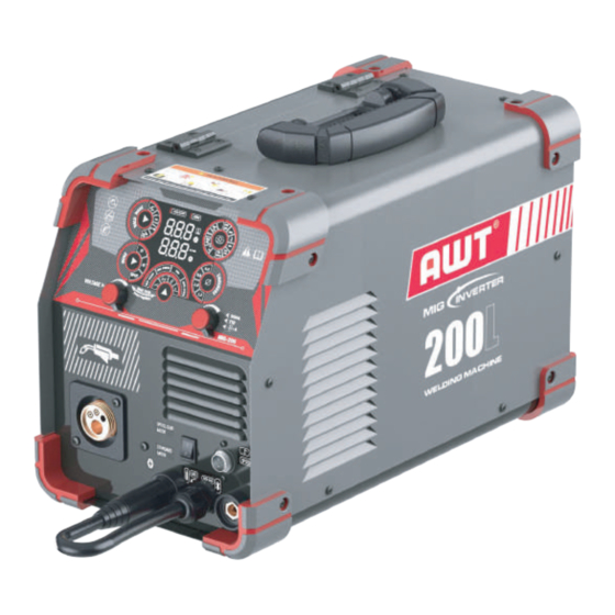
- Page 1 MIG-200 IGBT Inverter Welding Machine(GAS MIG, FLUX-CORED, SPOOL GUN COMPATIBLE MIG, STICK, LIFT TIG) OPERATOR’S MANUAL READ AND UNDERSTAND ALL INSTRUCTIONS AND PRECAUTIONS BEFORE PROCEEDING.
- Page 2 The AWT MIG-200 WELDER is designed for hobbyist or the busy profes- sional with the versatility to MIG, Stick or Lift TIG weld all from a single compact, space-saving and lightweight unit combined with self-sensing, dual-voltage capability for go anywhere convenience. The latest IGBT...
-
Page 3: Table Of Contents
CONTENTS 1.PACKING 2.SAFETY PRECAUTIONS - READ BEFORE USING 2.1 Symbol Usage 2.2 Arc Welding Hazards 2.3 Principal Safety Standards 3.PRODUCT DESCRIPTION 3.1 Function overview 3.2 Premium Feature 3.3 Technical Specifications 3.4 System Characteristics 4.OPERATION CONTROL AND DESCRIPTION 5 INSTALLATION SET UP AND OPERATION 5.1 MIG Welding Set-up And Operation 5.2 Stick Welding Set-up And Operation 5.3 Lift TIG Welding Set-up And Operation... -
Page 4: Packing
1.PACKING 1.MIG-200 Welder 2.110V~220V Adapter Cord 3.Hose Band*2 4.Ground Clamp With 10'(3m) Cable 5.MIG Torch With 10'(3m) Cable (.030"/0.8mm Contact Tip Installed) 6.Electrode Holder With 10'(3m) Cable 7.Brush/Hammer 8.Gas Hose 8'(2.5m) 9.W Knurl Groove Drive Roller: .030"/.035"(on the machine) 10. V Knurl Groove Drive Roller: .023"/.030", 0.30"/.035"... -
Page 5: Safety Precautions - Read Before Using
2.2 Arc Welding Hazards Welding can be dangerous to you and other persons in the work area. Read and understand this instruction manual before using your AWT welding machine. Injury or death can occur if safe welding practices are not followed.The symbols shown below are used throughout this manual to call attention to and identify possible hazards. - Page 6 Fumes And Gases Can Be Hazardous Welding produces fumes and gases. Breathing these fumes and gases can be hazardous to your health. Keep your head out of the fumes. Do not breathe the fumes. Work in a confined space only if it is well ventilated, or while wearing an air-sup- plied respirator.
-
Page 7: Principal Safety Standards
Exposure to electromagnetic fields while welding may have other health effects which are not known. FLYING METAL or DIRT can injure eyes. Welding, chipping, wire brushing, and grinding cause sparks and flying metal. As welds cool, they can throw off slag. Wear approved safety glasses with side shields even under your welding helmet. -
Page 8: Product Description
3.PRODUCT DESCRIPTION 3.1 FUNCTION OVERVIEW Versatility Synergic MIG: Automatic matching of the voltage & wire feeding speed by adjusting wire diameter,material and gas. 6 in 1 Multi-functions: Gas MIG/Flux Cored/MMA /LIFT TIG/Spot welding/Spool Gun are available. 2T/4T: Realize wide application, easy welding and continuous long-term welding. Inductance Adjustment: Improve welding performance. -
Page 9: Technical Specifications
3.3 TECHNICAL SPECIFICATIONS Model TECHNICAL PARAMETER Units MIG-200 Rated Input Voltage AC 110V ±15% 50/60 HZ AC 220V ±15% 50/60 HZ Rated Input Power 4.2KVA 8KVA Rated Input Current 25A-108A MMA Welding Current Range 25A-180A TIG Welding Current Range 15A-120A... - Page 10 MIG WELDING WIRE MIX Fe FLUX MIX SS AL Ar Cu Ar STEEL STEEL ALUMINUM FLUX CORED Stainless Steel Copper MATERIAL Solid Solid E71T-GS AlMg ER5356 Cu-Si S211 Wire Type ER70S-6/E50-6 ER70S-6/E50-6 .023"/.030" .023"/.030" .030"/.035" .030"/.035" .035"/.040" .035"/.04" .035"/.040" .035"/.040" .040"...
-
Page 11: System Characteristics
The rated Duty cycle refers to the amount of welding that can be done within an amount of time. The AWT MIG-200 has a duty cycle of 40% at 200 Amps for 220 Volts. It is easiest to look at your welding time in blocks of 10 Minutes and the Duty Cycle being a percentage of that 10 Minutes. -
Page 12: Operation Control And Description
4.OPERATION CONTROL AND DESCRIPTION eld mode and display area for Manual MIG /Synergic MIG/MMA/LIFT TIG button MIG operation Mode selection area Voltage knob MIG/ MMA function adjustment LIFT TIG m/min SPOT Material and gas selection button MIG welding Wire diameter selection Switch for Spool gun mode or Standard mode Cooling Fan - 10 -... - Page 13 Note: Please follow this connection. If the connection is incorrect it will cause the wire feeder to reverse - 11 -...
- Page 14 (50Amp @ 110V/ 50 Amp @ 220V) circuit breaker. CONTROL AND DISPLAY PANEL The MIG-200 Front Panel is equipped with Five Function Controls, One Digital Display and Two Value Knob (FIG 1). They are as follows:...
- Page 15 Button[4]: Press the button switching welding wire diameter.023"(0.6mm)/.030"(0.8mm)/ .040"(1.0mm)/ .045"(1.2mm) Note: Synergic MIG and Manual MIG allow the operation of different wire sizes. Please read carefully. WELDING WIRE Synergy(SYN) mode Manual (MAN) mode SOLID .023"/.030"/.035"/.040" .023”/.030"/.035"/.040" FLUX CORE .030"/.035"/.040" .030"/.035"/.040" STAINLESS STEEL .030"/.035"/.040"...
- Page 16 MIG Mode Function Description Setting Range Adjust soft to hard arc sparking. Inductance -10% to +10% Slows the wire feed speed to a pre-set speed Preset speed before 0-10 m/min prior to arc initiation, improving arc starts. arc start Control sets time gas flow before welding. 0 to 2 seconds Pre-flow control Spot Welding Time...
- Page 17 Note: Welding Parameter Table(For Reference Only) MIG FLUX Welding Wire Diameter Plant Thickness Adjust Current Adjust Voltage 1.0-2.0mm 40-80A 16-18V 0.8mm 2.0-3.0mm 80-120A 18-20V 3.0-4.0mm 120-150A 20-21.5V 1.2-2.0mm 60-80A 17-18V 2.0-3.0mm 80-120A 18-20V 1.0mm 3.0-4.0mm 120-150A 20-21.5V 4.0-8.0mm 150-200A 21.5-23V MIG CO₂...
- Page 18 MIG Ar Cu Welding Wire Diamete Plant Thickness Adjust Current Adjust Voltage 1.2-2.0mm 60-80A 17-18V 2.0-3.0mm 80-120A 18-20V 1.0mm 3.0-4.0mm 120-150A 20-21.5V 4.0-8.0mm 150-200A 21.5-23V Electrode Diameter Plant Thickness Adjust Current Adjust Voltage 1.0mm 1.0-2.0mm 25-50A 21-22V 1.6mm 1.5-2.5mm 40-70A 21.6-22.8V 2.0mm 2.0-3.5mm...
- Page 19 Manual MIG Choose spool gun mode or standard mode(MIG torch), set rocker switch FIG2 that is inner of the machine. (FIG2). Set the button [1] to Manual MIG. Set the button [2] to 2T/4T/spot. Set button [3] to choose the welding data(CO Fe/MIX Fe/FLUX/MIX SS/AL Ar/Cu Ar).
- Page 20 Set the button [5] to inductance, Slow Speed Wire Feeding Control, Post flow Control, spot welding time(spot welding time is only in the spot mode) Adjust the current knob [6] according to welding chart,the wire feed speed and voltage will be auto fitted by weld data program.
-
Page 21: Installation Set Up And Operation
5 INSTALLATION SET UP AND OPERATION 5.1 MIG WELDING SET-UP AND OPERATION FIG3 FIG4 FLUX(DCEN) FIG5 Fe(DCEP) Mix Fe(DCEP) Mix SS(DCEP) Al Ar (DCEP) Cu Ar (DCEP) Set the button(1)to the SYN MIG or MAN MIG FIG6 DCEN DCEP - 19 -... - Page 22 lnstall A Spool Gun for Aluminum Welding FIG7 Remove the regular MIG torch and connect the EURO STYLE spool gun to the( ) , the other wire of the spool gun to the air socket( ).Locate the Ground Clamp with (-) on the Welder.(DCEP)Check the wire size on the torch and install the aluminum wire.Switch the button to spool gun mode.(FIG 2).
- Page 23 INSTALLING THE GROUND CABLE AND CLAMP FIG9 DCEP:Locate the Ground Clamp with Cable and connect the cable coupler end to the Negative Connector(-)on the Welder.DCEP@CO 100%, Ar/CO Mix, Ar100% DCEN:Locate the Ground Clamp with Cable and connect the cable coupler end to the Positive Connector(+) on the Welder.(DCEN @Flux) Align the key of the brass ferrule with the notch of the receptacle at the 12:00 position (FIG 9), insert the plug and...
- Page 24 FIG11 AWT MIG-200 AWT MIG-200 AWT MIG-200 FIG12 FIG13 AWT MIG-200 AWT MIG-200 - 22 -...
- Page 25 AWT MIG-200 FIG14 MIG-200 (FIG 14) FIG15 (FIG 15) (FIG 16) (FIG 14) FIG16 (FIG 14) AWT MIG-200 Using spool gun(not included) need to set the rocker switch that is inner of the machine. (FIG 2) - 23 -...
- Page 26 Installation of 4"(100mm) wire spool Spindle Spool Spool spacer Spring Spool lock Installation of 8"(200mm) wire spool Spindle Spool Spool spacer Spring Spool lock - 24 -...
- Page 27 MIG WELDING OPERATION Your AWT MIG-200 can be used to form many different joints and welds all of which will require practice and testing before using on an actual project piece. This following welding process is just a baseline to get you started.
- Page 28 Connect your ground clamp to the work pieces that are to be welded. Make sure the ground clamp contacts are placed on a clean piece of metal free of paint, grease, rust, oils, etc. It is recom- mended to place your ground clamp as close to the weld area as possible. Assess your weld area and make sure the welding area is also cleaned of any paint, grease, rust, oils, etc.
-
Page 29: Stick Welding Set-Up And Operation
HEAVY GAUGE METAL WELDING TECHNIQUES When welding heavy gauge metal, a continuous bead is formed using a ‘push’ method. This process is described below: Clean the metal to be welded of any paint, rust, oil, grease, dirt or any other contaminants that may be on the surface of the piece. - Page 30 POLARITY SELECTION The AWT MIG-200 can weld in both Direct Current Electrode Positive (DCEP) and Direct Current Electrode Negative (DCEN). The electrode, or rod, when welding in DCEP is positive and the grounded surface is negative. This polarity is used with electrodes that specify it and is usually the most commonly used polarity when ARC welding for general purpose use.
-
Page 31: Lift Tig Welding Set-Up And Operation
STICK WELDING PROCEDURE Set up a clean will lit work area. Prepare the parts to be welded by cleaning the weld joint area of any rust, dirt, grease, or paint. Select the proper electrode for the weld joint. Turn on the Welder and select the appropriate amperage. To determine proper amperage it is best to practice on some similar metals to set up the machine before welding on an actual part of value. - Page 32 AWT MIG-200 MIG-200 AWT MIG-200 (FIG 11). (FIG 12). 12). FIG19 FIG20 Rotate the knob on the gun to adjust the gas. (FIG 19). - 30 -...
- Page 33 FIG21 (FIG20). FIG22 MIG-200 (FIG21). (FIG22). Button(1) - 31 -...
- Page 34 Lift TIG WELDING AWT MIG-200 - 32 -...
-
Page 35: Overload Protection
5.4 OVERLOAD PROTECTION Our AWT MIG-200 Welder is equipped with over load protection system which will protect your Welder if the duty cycle is exceeded. If the output is exceeded, the system will trip and stop power supply to the drive motor although the fan will still run to cool the unit. Allow the Welder to cool for a minimum of 15 minutes before attempting to resume welding. -
Page 36: Troubleshooting
Move the Contact Tip on the Welding Gun closer to the Excessive Wire Lack of work piece to shorten the length of exposed wire. Protruding Penetration The MIG-200 is rated for a maximum thickness of 3/8", ex- Material Too Thick ceeding this will result in poor penetration. - 34 -... - Page 37 If welding heavy gauge metals, it may be necessary to in- crease the welding gap between the two pieces and also Poor Material Prep bevel the edges on the weld side of the pieces. High Voltage Adjust voltage output to lower setting. Excessive Adjust wire speed to slower setting.
- Page 38 Adjust the flow rate of the shielding gas. Check for loose fit- Poor Gas Flow tings where gas could be leaking. Clean filler metal making sure to remove any oil, debris, or Contaminated Filler Metal moisture. Clean base metal making sure to remove any oil, debris, Contaminated Porosity in Filler Metal...
- Page 39 TIG WELDING TROUBLESHOOTING PROBLEM CAUSE CORRECTION Keep the Torch on the base metal while the post flow Insufficient shielding gas flows to protect and cool the metal and Shielding Crater in the Tungsten. End of the Reduce current and add more filler at end of weld. It may Weld Bead Not Enough also be beneficial to back step to ensure no crater will...
- Page 40 VRD:Protection against electric shock - 38 -...
-
Page 41: Diagram
7.DIAGRAM AC Rectifier 475/400V 150K/2512 150K/2512 Thermal protect 10R/2512 471/2KV 枪开关 10R/2512 OUT- OUT+ 106/250V Main transformer - 39 -...
Need help?
Do you have a question about the MIG-200 and is the answer not in the manual?
Questions and answers