
Related Manuals for AWT MIG-140PRO


Summary of Contents for AWT MIG-140PRO
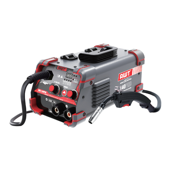
- Page 1 MIG-140PRO Inverter Welding Machine(FLUX-CORED , STICK, LIFT TIG) OPERATOR’S MANUAL READ AND UNDERSTAND ALL INSTRUCTIONS AND PRECAUTIONS BEFORE PROCEEDING.
-
Page 2: Table Of Contents
CONTENTS 1.PACKING 2.SAFETY PRECAUTIONS - READ BEFORE USING 2.1 Symbol Usage 2.2 Arc Welding Hazards 3.PRODUCT DESCRIPTION 3.1 How To Use This Manual 3.2 Receipt of Equipment 3.3 Description 3.4 Duty Cycle 3.5 TECHNICAL SPECIFICATIONS 4 INSTALLATION 4.1 Installation and Setup For MIG with Gas less 5 OPERATION 6.MAINTENCE 7.TROULBESHOOTING... -
Page 3: Packing
1.PACKING 1.MIG Welder 2.MIG Torch With 10ft (3m) cable 3.Ground clamp with 10ft (3m) cable 4.Electrode holder with 10ft (3m) cable 5..030"/2lbs Flux Cored Wire 6.Brush/hammer 7.Knurl Groove Drive Roller: .030”/.035”(on the machine) 8.Contact tip: .030” & .035” 9.Nozzle - 2 -... -
Page 4: Safety Precautions - Read Before Using
2.2 Arc Welding Hazards Welding can be dangerous to you and other persons in the work area. Read and understand this instruction manual before using your AWT welding machine. Injury or death can occur if safe welding practices are not followed.The symbols shown below are used throughout this manual to call attention to and identify possible hazards. - Page 5 Fumes And Gases Can Be Hazardous Welding produces fumes and gases. Breathing these fumes and gases can be hazardous to your health. Keep your head out of the fumes. Do not breathe the fumes. Work in a confined space only if it is well ventilated, or while wearing an air-supplied respirator.
- Page 6 Exposure to electromagnetic fields while welding may have other health effects which are not known. FLYING METAL or DIRT can injure eyes. Welding, chipping, wire brushing, and grinding cause sparks and flying metal. As welds cool, they can throw off slag. Wear approved safety glasses with side shields even under your welding helmet.
-
Page 7: Product Description
The rated Duty cycle refers to the amount of welding that can be done within an amount of time. The AWT MIG-140 Pro has a duty cycle of 25% at 120 Amps for 110 Volts. It is easiest to look at your welding time in blocks of 10 Minutes and the Duty Cycle being a percentage of that 10 Minutes. -
Page 8: Technical Specifications
3.5 TECHNICAL SPECIFICATIONS Model TECHNICAL PARAMETER Units MIG-140PRO Rated Input Voltage AC 110V+15% 50/60Hz Rated Input Power 4.1KVA Rated Input Current 36.5A MMA Welding Current 20A~115A TIG Welding Current 15A~115A MIG Welding Current 40A~120A No-Load Voltage Rated Duty Cycle Enclosure Protection... -
Page 9: Installation
4 INSTALLATION MIG-140PRO MIG-140PRO MIG-140PRO MIG-140PRO - 8 -... -
Page 10: Installation And Setup For Mig With Gas Less
MIG-140PRO 4.1 Installation and Setup For MIG with Gas less [1] Ensure that the power switch is “OFF". [2] Connect the weld power cable and tighten it. [3] Connect the earth clamp into the Positive socket(+)and tighten it. IMPORTANT:Loose welding terminal connections can cause overheating and result in the male plug being fused in the terminal. - Page 11 1.Power switch 2.Connect power cable 3.connect earth clamp 4.Install the correct knurled drive roller for gas less flux core wire. Wire diameter must be matched to the drive roller and contact tip. 5-6. Place wire onto spool holder(spool retaining nut is top thread). Feed the wire through the inlet guide tube on to the drive roller.
- Page 12 7-8. Close down the top roller bracket and clip the pressure arm into place. Apply a medium amount of pressure to the drive roller 9-11.Remove the nozzle and contact tip from the front end of the MIG torch.Press and hold the MIG Torch switch to feed the wire through to the torch neck.
-
Page 13: Wire Loading And Threading
Wire Loading and Threading Turn machine power switch to the OFF position before working inside the wire feed enclosure. Make sure that the wire feed drive roll and the contact tip of the gun match the diam- eter and type of wire used. Installation of Wire Spool 1) Push the spool onto the spindle so that the wire deeds off the bottom of the spool,... - Page 14 Warning When feeding the welding wire through the gun, the drive roll, the gun connector block and the gun contact tip are always energized relative to work and ground. Wire Stick Out 7) Remove the contact tip and nozzle from the gun. 8) Turn the machine ON .
-
Page 15: Lift Tig Welding
TIG WELDING STICK WELDING (MMA) 1.Ensure that the power switch is “OFF" 1.Ensure that the power switch is “OFF" 2)A primary power supply cable is available 2)A primary power supply cable is available for this welding machine. Connect the power for this welding machine. -
Page 16: Operation
5.OPERATION - 15 -... -
Page 17: Controls And Operational Features
5.OPERATION CONTROLS AND OPERATIONAL FEATURES 1.Current Display 2.Voltage Adjustment 3.Amp/Wire Feed Knob 4.Welding Mode Selection 5.Power Light 6.Over Heating Protection Indication 7.MIG Gun Socket 8.Positive Output Terminal FLUX 9.Negative Output Terminal 10.Input Power Cable 11.Power Switch 12.Cooling Fan MODEL MIG-140-2 №: UL60974 20A/15V~120A/20V... -
Page 18: Front Panel Controls
5.OPERATION FRONT PANEL CONTROLS 1.Power Light The Power indicator will not illuminate on when the power source is on. It will be on when trigger the torch switch. 2.Protection Indicator This indicator will turn on when the machine is overheated or over-current. When the indicator turns off, normal operation is again. - Page 19 5.OPERATION 6.Amp Display Display of MMA TIG and Flux-core Amp 7.SYN light Synergic mode. The light will turn on when you press and hold button 3 for 3 seconds. Synergic MIG welding, the wire feed speed and Voltage will be auto fitted by adjusting wire diameter.
- Page 20 5.OPERATION The joint to be welded must be clean,remove existing rust, greasy dirt, water and paint etc. Flux-core(Gasless) Synergic MIG Press and hold button”choose” for 3 seconds start to “synergic” function. Press “choose” button on Flux wire .030”/.035” The wire feed speed and Voltage will be auto fitted by adjusting wire diameter. Point the wire into the joint to be weld, press down the gun trigger, the wire feeds automatically.
-
Page 21: Maintence
6.MAINTENCE - 20 -... - Page 22 6.MAINTENCE - 21 -...
-
Page 23: Troulbeshooting
7.TROULBESHOOTING -22 -... -
Page 24: Circuit Diagram
8.CIRCUIT DIAGRAM Thermal protect 475/400V torch switch OUT- 10R/2512 471/2KV R024 R023 OUT+ IGBT 10R/2512 R010 R011 IGBT 475/250V C015 T50*25*25 13:5 -23 -...
Need help?
Do you have a question about the MIG-140PRO and is the answer not in the manual?
Questions and answers