
Subscribe to Our Youtube Channel
Related Manuals for ChlorKing NEXGEN20


Summary of Contents for ChlorKing NEXGEN20
- Page 1 NEXGEN20 and 20R Installation, Operation, and Maintenance Manual 03/30/2022 NEX-GEN20 InstallationREV3 Page 1 of 39...
-
Page 2: Table Of Contents
Routine Maintenance Cell Cleaning Procedure 5.0 WARRANTY INFORMATION Note: This manual is subject to change at any time based on system improvements, design changes, authorized modifications or new information. Please consult ChlorKing for the latest revision. Manufacturer: ChlorKing Inc 2935 Northeast Parkway... -
Page 3: Description
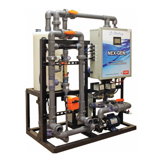
SECTION 1 DESCRIPTION 1.1 GENERAL INFORMATION The NEXGEN system is an on-site sodium hypochlorite generator designed for commercial swimming pool applications. The NEXGEN can produce up to 24 pounds of equivalent chlorine per day. The system manufactures bleach continuously from a salt concentration of 5000ppm to 7000ppm and uses the water from the pool as a raw material. -
Page 4: Principals Of Operation
1.2 PRINCIPALS OF OPERATION Production Tank Assembly The production tank assembly consists of a polyethylene tank, an external electrolytic cell, a circulation pump and heat exchanger. Pool water from the pool return line is fed into the production tank. The circulation pump circulates water through the electrolytic cell and heat exchanger. - Page 5 1.3 GENERAL SPECIFICATIONS Sodium hypochlorite production: NEXGEN20 - Up to 24 pounds per day at 7000ppm NEXGEN20R – Up to 24 pounds per day at 7000ppm Maximum pool return line pressure: 25 PSI including plumbing to and from the venturi injector...
- Page 6 DIMENSIONS 03/30/2022 NEX-GEN20 InstallationREV3 Page 6 of 39...
-
Page 7: Installation
AND DISCONNECTED FROM THE POWER SOURCE AND ALL PRESSURE BLED FROM THE LIQUID LINES. WARNING CHLORKING® SYSTEMS ARE INTENDED TO BE INSTALLED ACCORDING TO ALL LOCAL AND NATIONAL REGULATIONS. CONNECT THE EQUIPMENT ASSEMBLY TO A CIRCUIT PROTECTED BY A GROUND-FAULT CIRCUIT-INTERRUPTER. - Page 8 ONLY A CERTIFIED TECHNICIAN MAY INSTALL AND SERVICE THE CHLORKING® NEXGEN SYSTEM. MODIFYING THE CHLORKING® NEXGEN SYSTEM IN ANY WAY MAY CAUSE BODILY INJURY AND WILL VOID THE WARRANTY. DO NOT ALLOW CHILDREN OR ANYONE NOT CAPABLE TO OPERATE THE CHLORKING®...
-
Page 9: Plan Ahead
CHLORKING ® SYSTEMES SONT DESTINES A ETRE INSTALLES SELON TOUS LES REGLEMENTS LOCAUX ET NATIONAUX. CONNECTER LE MONTAGE DE L'ÉQUIPEMENT SUR UN CIRCUIT PROTÉGÉ PAR UN DISJONCTEUR DE FUITE À LA TERRE. SEUL UN TECHNICIEN CERTIFIE PEUT INSTALLER ET ENTRETENIR LE ... -
Page 10: Power Supply Electrical Connections
CURRENT. ENSURE THAT POWER IS LINKED TO THE MAIN PUMP POWER SOURCE FOR THE POOL TO ENSURE THAT YOUR CHLORKING® NEXGEN SYSTEM NEVER OPERATES WHEN THE POOL PUMPS ARE OFF. For ease of service, it is recommended that a manual disconnect be installed between the electrical service and the NEXGEN system. -
Page 11: Bonding
Connect the blue control cord to a chemical feed controller or for manual operation, into a 120V electrical outlet protected by a ground fault circuit interrupter. Blue Controller Cord Bonding Lugs 2.7 BONDING Connect a minimum 8awg bonding wire to the bonding lug on the bottom of the electrical enclosure. -
Page 12: Plumbing Connections
NEXGEN with the cable provided and to the pump according to the instructions on the pump for 208/240 VAC connections. The NEXGEN ships with a 12amp breaker for a 1HP pump. Larger pumps will require changing the breaker. Contact ChlorKing for breaker sizing. 03/30/2022 NEX-GEN20 InstallationREV3... - Page 13 The pressure connection should provide a minimum of 5 psi when the pool pump is on, and pressure should be less than 3 psi when the pool pumps are off. Contact ChlorKing for installations that do not meet these specifications. 03/30/2022...
-
Page 14: Saturated Salt Feeder Installation
2.9 SATURATED SALT FEEDER INSTALLATION Place the Saturated Salt Feeder tank in an easy to access location. The tank will need access for adding salt on a continuous basis. Plumb the peristaltic pump suction line to the salt outlet on the Saturated Salt Feeder with 1/4 tubing supplied with the peristaltic pump. - Page 15 Install the overflow with the T provided in the installation kit. This T will remain open on top to prevent syphoning in case of tank overflow. The bottom of the T receives a 1” FPT low pressure connection with hose directed to a floor drain, drain tube is not provided.
-
Page 16: Preparing The Ph Neutral System
Use a minimum of 2 inch pipe for the vent. The vent pipe should not be longer than 100 feet. (Consult ChlorKing if longer runs are required). Keep the opening clear and protected from water or debris with the use of a hood or bend. -
Page 17: Operation
SECTION 3 OPERATION 3.1 START-UP PROCEDURES AND CHECKS Check that all components are mounted securely. Check that all plumbing is secure and tight. Check that all plumbing and electrical connections are connected in the proper place. Ensure that all system isolation valves installed during installation are open. Fill the Saturated Salt Feeder with pure rock or pellet salt. -
Page 18: Touch-Screen Icon Explanations
3.3 TOUCH SCREEN ICON EXPLANATIONS This icon is displayed if the system is turned off. This icon is displayed if the system is waiting for a signal from an external controller. This icon is displayed if cell cleaning mode has been selected. This icon will be displayed until the cell cleaning process is complete. -
Page 19: Using The Touchscreen
3.4 USING THE TOUCHSCREEN Home Screen Below is the HOME screen that will be displayed any time the NEXGEN is operating normally. Process Tank Pool Feed Temperature Indicator On/Off Indicator On/Off Button Process Tank pH Electrolytic Cell Volts Process Menu Button Tank Salt Electrolytic Level... - Page 20 Turning the NEXGEN On or Off To turn the system on or off, press and hold the ON/OFF button until the desired ON/OFF indicator is displayed. The NEXGEN may take several minutes to completely turn on or off. On/Off Indicator On/Off Switch The Menu...
- Page 21 The Service Screen Press MENU then SERVICE to access the SERVICE screen. The service screen has the option to view the current state of the system OUTPUTS, the current state of the system INPUTS, to manually TEST system outputs, to view or set system SETPOINTS, and to view recorded data.
- Page 22 View System Analog Inputs Press MENU then SERVICE then INPUTS then ANALOG INPUTS to display the current value of all analog inputs. The letters inside of the dot indicates the actual input number on the PLC. View System Outputs Press MENU then SERVICE then OUTPUTS to display the current state of all outputs. An active output is indicated by an icon next to the output name.
- Page 23 System Tests Note: Selecting the TEST screen will turn the NEXGEN system off. Press MENU then SERVICE then TEST to view the test screen. Press NEXT for the second TEST screen. The following components can be manually operated for testing from these screens.
- Page 24 Viewing or Changing Set-points Press MENU then SERVICE then SETPOINT to access the set-point screen. From this screen the SALT SETPOINT, PH SETPOINT, ACID FEED TIME, and MINIMUM SALINITY can be adjusted. The factory default is 7000 for salt, 7.4 for pH, and 60 seconds for feed time.
- Page 25 Accessing Graphs Press MENU then SERVICE then GRAPHS to access the graphs screen. From this screen process temperature, process pH, and low pH can be seen over history. Accessing the Current Event Log Press MENU then EVENTS to access the current event log. This screen lists current events or faults.
-
Page 26: Maintenance
SECTION 4 MAINTENANCE 4.1 ROUTINE MAINTENANCE Daily Confirm system operation with a visual inspection. Check the salt concentration on the display. Check the amps as displayed on the gauge. Check the flow through the flow meter. Weekly Clean the electrode stacks each week or as needed based on the presence of calcium buildup. - Page 27 Note: Sulfuric acid and dry acid (sodium bisulfate) are not recommended for cell cleaning. Under some conditions the electrolytic cell can be damaged. WARNING Read all cautions and directions provided with the muriatic acid used. Always add acid to water. Use only with adequate ventilation. If strong odor is noticed, STOP, ventilation is inadequate.
- Page 28 STEP 2 – During this step the booster pump will start and the product tank will empty. When the tank is empty the GREEN Low Level Sw will turn RED. When the tank has emptied the TANK EMPTY will be displayed. Press NEXT to continue.
- Page 29 STEP 3 – Close the Cell Output Valve marked 8 and the Pump Isolation Valve marked 7. Close Valve 8 Press NEXT to continue. Cell Output Valve Close Valve 7 Pump Isolation Valve STEP 4 – Connect Acid Wash Inlet Coupling to the Acid Wash Inlet Valve colored White. Connect Acid Wash Outlet Coupling to the Acid Wash Outlet Valve colored Gray.
- Page 30 STEP 5 – Open the Acid Wash Inlet and Outlet Valves. Press NEXT to continue. Open Acid Wash Outlet Valve Open Acid Wash Inlet Valve STEP 6 – Open both White Acid Wash Valves on the Acid Wash assembly. Press NEXT to continue. Open White Acid Wash Valve...
- Page 31 STEP 7 – Close both Gray Acid Wash Valves on the Acid Wash assembly. Press NEXT to continue. Close Gray Close Gray Acid Wash Acid Wash Valve Valve STEP 8 – Plug the Acid Wash Assembly into the Special Power Connector and turn on the Acid Wash Pump on the skid.
- Page 32 STEP 9 – Press the blue “Press to Acid Wash” button. The Acid Wash assembly will begin to fill the NEXGEN with muriatic acid and circulate the acid through the cells for as long as 30 minutes. If the cells are clean before the 30 minute time interval has expired, press the blue Acid Wash button to stop the process.
- Page 33 STEP 11 – Close both White Acid Wash Valves on the Acid Wash assembly. Press NEXT to continue. Close White Acid Wash Valve Close White Acid Wash STEP 12 – Press the blue “Press to Drain” button. The Acid Wash assembly will begin to drain the muriatic acid from the NEXGEN.
- Page 34 STEP 14 – Close the Acid Wash Inlet and Outlet Valves. Close Acid Press NEXT to continue. Wash Outlet Valve Close Acid Wash Inlet Valve STEP 15 – Unplug the Acid Wash Assembly from the Special Power Connector. Press NEXT to continue. 03/30/2022 NEX-GEN20 InstallationREV3 Page 34 of 39...
- Page 35 STEP 16 – Disconnect Acid Wash Coupling Inlet and Outlet from the Acid Wash Inlet and Outlet Valves. Acid Wash Press NEXT to continue. Outlet Valve Acid Wash Inlet Valve STEP 17 – Open Cell Output Valve marked 8 and the Pump Isolation Valve marked 7. Press NEXT to continue.
- Page 36 STEP 18 – This step will empty any remaining acid from the cells. When the process is complete CELL EMPTY will be displayed. Press NEXT to continue. STEP 19 – Open Valve 3 the Tank Fill Valve. Press NEXT to continue. Open Valve 3 Tank Fill Valve...
- Page 37 STEP 20 – This step will fill and flush the system. Once filling and flushing is complete, the current system pH will be displayed and you will be prompted to press NEXT to continue. STEP 21 – Adjust the Production Flow Valve marked 4 to the desired flow rate outlined in Section 3.2 on page 17.
- Page 38 STEP 22 – Cell cleaning is finished. Press NEXT to continue. The home screen will be displayed. The NEXGEN will start automatically. The startup process will include automatic adjustment of the pH and salt concentration in the production tank. Once this process is complete the NEXGEN will resume normal operation.
-
Page 39: Warranty Information
SECTION 5 WARRANTY INFORMATION ChlorKing® NEXGEN system carries a limited 3-year warranty 1. 3-year warranty on assembly of the system. 2. 1 year on all electrical items, cell tubes, and production tanks. 3. 2 years pro-rated monthly, on titanium electrodes. (Year 1 is warranted fully, thereafter pro-rated warranty applies, applicable over the full 2-year period.
Need help?
Do you have a question about the NEXGEN20 and is the answer not in the manual?
Questions and answers