
Related Manuals for ChlorKing NEXGEN40


Summary of Contents for ChlorKing NEXGEN40
- Page 1 NEXGEN40 and 40R Installation, Operation, and Maintenance Manual 04/11/2022 NEXGEN40 InstallationREV3 Page 1 of 39...
-
Page 2: Table Of Contents
Cell Cleaning Procedure 5.0 WARRANTY INFORMATION Note: This manual is subject to change at any time based on system improvements, design changes, authorized modifications, or new information. Please consult ChlorKing for the latest revision. Manufacturer: ChlorKing Inc 2935 Northeast Parkway... -
Page 3: Description
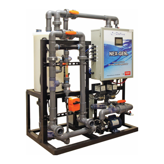
24 hours a day or controlled by any pool controller. “R” models are reverse polarity for reduced maintenance. The basic components of the NEXGEN are outlined below. Production Tank Power Supply and Control Box Chemical Metering 04/11/2022 NEXGEN40 InstallationREV3 Page 3 of 39... -
Page 4: Principals Of Operation
The power supply provides the current to the electrolytic cells to produce the rated amount of sodium hypochlorite. The power supply houses all the safety features to prevent system operation in the event of a malfunction. 04/11/2022 NEXGEN40 InstallationREV3 Page 4 of 39... - Page 5 CSA Standard C22.2 #218.1 PRMA Reg. No. 33004 Sizing guidelines Chlorinator sizing must comply with local codes. Please contact your local health department for specific requirements or contact your local ChlorKing representative for assistance. 04/11/2022 NEXGEN40 InstallationREV3 Page 5 of 39...
- Page 6 DIMENSIONS 04/11/2022 NEXGEN40 InstallationREV3 Page 6 of 39...
-
Page 7: Installation
FROM THE LIQUID LINES. WARNING CHLORKING® SYSTEMS ARE INTENDED TO BE INSTALLED ACCORDING TO ALL LOCAL AND NATIONAL REGULATIONS. CONNECT THE EQUIPMENT ASSEMBLY TO A CIRCUIT PROTECTED BY A GROUND-FAULT CIRCUIT-INTERRUPTER. 04/11/2022 NEXGEN40 InstallationREV3 Page 7 of 39... - Page 8 LE CONTENU DE CE MANUEL. AUCUNE OPÉRATION DE MAINTENANCE DE CET ÉQUIPEMENT DOIT ÊTRE FAITE AVEC L'UNITÉ ENTIÈREMENT ÉTEINT ET DÉBRANCHÉE DE L'ÉLECTRICITÉ ET TOUTE LA PRESSION SAIGNÉ À PARTIR DES LIGNES DE LIQUIDES. MISE EN GARDE 04/11/2022 NEXGEN40 InstallationREV3 Page 8 of 39...
-
Page 9: Plan Ahead
PVC 90’s, 45’s, couplings and saddles or adapters for the return line size encountered 2 inch PVC pipe, 90’s, 45’s and couplings for the hydrogen vent Anchors and mounting hardware Container specified for muriatic acid solutions 04/11/2022 NEXGEN40 InstallationREV3 Page 9 of 39... -
Page 10: Power Supply Electrical Connections
240 VAC L1, L2 and ground. Ensure that the electrical service is protected by a circuit interrupter and is rated for the model NEXGEN that is installed. Ground 240 VAC 240 VAC L1 and L2 L1 and L2 04/11/2022 NEXGEN40 InstallationREV3 Page 10 of 39... -
Page 11: Bonding
120V electrical outlet protected by a ground fault circuit interrupter. Blue Controller Cord Bonding Lugs 2.7 BONDING Connect a minimum 8awg bonding wire to the bonding lug on the bottom of the electrical enclosure. 04/11/2022 NEXGEN40 InstallationREV3 Page 11 of 39... -
Page 12: Plumbing Connections
NEXGEN with the cable provided and to the pump according to the instructions on the pump for 208/240 VAC connections. The NEXGEN ships with a 12amp breaker for a 1HP pump. Larger pumps will require changing the breaker. Contact ChlorKing for breaker sizing. 04/11/2022 NEXGEN40 InstallationREV3... - Page 13 The pressure connection should provide a minimum of 5 psi when the pool pump is on, and pressure should be less than 3 psi when the pool pumps are off. Contact ChlorKing for installations that do not meet these specifications. 04/11/2022...
-
Page 14: Saturated Salt Feeder Installation
The salt outlet on the Saturated Salt Feeder is a small Plumb the Saturated Salt blue and white valve located at the bottom of the salt feeder. Feeder water supply to the fitting on the chemical metering assembly using ½ inch tubing. 04/11/2022 NEXGEN40 InstallationREV3 Page 14 of 39... - Page 15 The bottom of the T receives a 1” FPT low pressure connection with hose directed to a floor drain, drain tube is not provided. 04/11/2022 NEXGEN40 InstallationREV3 Page 15 of 39...
-
Page 16: Preparing The Ph Neutral System
Use a minimum of 2 inch pipe for the vent. The vent pipe should not be longer than 100 feet. (Consult ChlorKing if longer runs are required). Keep the opening clear and protected from water or debris with the use of a hood or bend. -
Page 17: Operation
7000 ppm salt concentration and 2.4 GPM. Adjustments in excess of 2.4 gallons per minute will not produce more chlorine. Adjustments in excess of 2.4 gallons per minute will only consume excess salt. 04/11/2022 NEXGEN40 InstallationREV3 Page 17 of 39... -
Page 18: Touch-Screen Icon Explanations
Press this icon to clear the fault described above. This icon indicates that acid is being pumped during the cell cleaning cycle. Faults are accompanied by a beeping sound. If this icon is visible, pressing it will stop the beeping sound. 04/11/2022 NEXGEN40 InstallationREV3 Page 18 of 39... -
Page 19: Using The Touchscreen
Below is the HOME screen that will be displayed any time the NEXGEN is operating normally. Process Tank Pool Feed Temperature Indicator On/Off Indicator On/Off Button Process Tank pH Electrolytic Cell Volts Process Menu Button Tank Salt Electrolytic Level Cell Amps 04/11/2022 NEXGEN40 InstallationREV3 Page 19 of 39... - Page 20 The NEXGEN may take several minutes to completely turn on or off. On/Off Indicator On/Off Switch The Menu Press the MENU button to access the HOME, SERVICE and EVENTS buttons. Menu Button 04/11/2022 NEXGEN40 InstallationREV3 Page 20 of 39...
- Page 21 An active input is indicated by the GREEN dot next to the input name. A check mark indicates the parameter is OK. A RED dot indicates an inactive input. The number or letter inside of the dot indicates the actual input number on the PLC. 04/11/2022 NEXGEN40 InstallationREV3 Page 21 of 39...
- Page 22 Press MENU then SERVICE then OUTPUTS to display the current state of all outputs. An active output is indicated by an icon next to the output name. The number next to the output indicates the actual output number on the PLC. 04/11/2022 NEXGEN40 InstallationREV3 Page 22 of 39...
- Page 23 Pump and pH Reaction (Press for 2 seconds) Acid Wash Pump (Press for 2 seconds) Hydrogen Vent Blower and Flow Switch Feed Valve 1 Feed Valve 2 (ORP 2 must be active for this test) 04/11/2022 NEXGEN40 InstallationREV3 Page 23 of 39...
- Page 24 PH FEED TIME can be adjusted. The factory default is 60 seconds. Accessing the Recorded Event Log Press MENU then SERVICE then RECORD to access the event log screen. The event log will store every system event that has occurred by date and order. 04/11/2022 NEXGEN40 InstallationREV3 Page 24 of 39...
- Page 25 This screen will also activate automatically whenever a fault occurs. A current fault is displayed in black. Pressing the red ACKNOWLEDGE ALL EVENTS button and then the RESET ALARM button will reset all alarms. 04/11/2022 NEXGEN40 InstallationREV3 Page 25 of 39...
-
Page 26: Maintenance
Check the system filter (if installed), production tank filter (if installed), and dilution fan screen and clean as necessary. 4.2 CELL CLEANING PROCEDURE Press MENU then SERVICE then CLEAN CELLS to access step by step instructions for cleaning the cells. 04/11/2022 NEXGEN40 InstallationREV3 Page 26 of 39... - Page 27 STEP 1 – Close the Tank Fill Valve marked 3. Close the Product Flow Adjustment Valve marked 4. This will allow the tank to drain for cleaning. Press NEXT to continue. Valve 4 Product Flow Adjustment Valve Valve 3 Tank Fill Valve 04/11/2022 NEXGEN40 InstallationREV3 Page 27 of 39...
- Page 28 STEP 2 – During this step the booster pump will start and the product tank will empty. When the tank is empty the GREEN Low Level Sw will turn RED. When the tank has emptied the TANK EMPTY will be displayed. Press NEXT to continue. 04/11/2022 NEXGEN40 InstallationREV3 Page 28 of 39...
- Page 29 STEP 4 – Connect Acid Wash Inlet Coupling to the Acid Wash Inlet Valve colored White. Connect Acid Wash Outlet Coupling to the Acid Wash Outlet Valve colored Gray. Press NEXT to continue. Acid Wash Outlet Valve (Gray) Acid Wash Inlet Valve (White) 04/11/2022 NEXGEN40 InstallationREV3 Page 29 of 39...
- Page 30 Open Acid Wash Inlet Valve STEP 6 – Open both White Acid Wash Valves on the Acid Wash assembly. Press NEXT to continue. Open White Acid Wash Valve Open White Acid Wash Valve 04/11/2022 NEXGEN40 InstallationREV3 Page 30 of 39...
- Page 31 Acid Wash Acid Wash Valve Valve STEP 8 – Plug the Acid Wash Assembly into the Special Power Connector and turn on the Acid Wash Pump on the skid. Press NEXT to continue. 04/11/2022 NEXGEN40 InstallationREV3 Page 31 of 39...
- Page 32 Acid Wash button to stop the process. Press NEXT to continue. STEP 10– Open both Gray Acid Wash Valves on the Acid Wash assembly. Press NEXT to continue. Open Gray Open Gray Acid Wash Acid Wash Valve Valve 04/11/2022 NEXGEN40 InstallationREV3 Page 32 of 39...
- Page 33 STEP 12 – Press the blue “Press to Drain” button. The Acid Wash assembly will begin to drain the muriatic acid from the NEXGEN. When the draining is complete, CELL EMPTY will be displayed. Press NEXT to continue. 04/11/2022 NEXGEN40 InstallationREV3 Page 33 of 39...
- Page 34 STEP 14 – Close the Acid Wash Inlet and Outlet Valves. Close Acid Press NEXT to continue. Wash Outlet Valve Close Acid Wash Inlet Valve STEP 15 – Unplug the Acid Wash Assembly from the Special Power Connector. Press NEXT to continue. 04/11/2022 NEXGEN40 InstallationREV3 Page 34 of 39...
- Page 35 Inlet Valve STEP 17 – Open Cell Output Valve marked 8 and the Pump Isolation Valve marked 7. Press NEXT to continue. Open Valve 8 Cell Output Valve Valve 7 Pump Isolation Valve 04/11/2022 NEXGEN40 InstallationREV3 Page 35 of 39...
- Page 36 STEP 18 – This step will empty any remaining acid from the cells. When the process is complete CELL EMPTY will be displayed. Press NEXT to continue. STEP 19 – Open Valve 3 the Tank Fill Valve. Press NEXT to continue. Open Valve 3 Tank Fill Valve 04/11/2022 NEXGEN40 InstallationREV3 Page 36 of 39...
- Page 37 NEXT to continue. STEP 21 – Adjust the Production Flow Valve marked 4 to the desired flow rate outlined in Section 3.2 on page 17. Press NEXT to continue. Valve 4 Production Flow Valve 04/11/2022 NEXGEN40 InstallationREV3 Page 37 of 39...
- Page 38 The home screen will be displayed. The NEXGEN will start automatically. The startup process will include automatic adjustment of the pH and salt concentration in the production tank. Once this process is complete the NEXGEN will resume normal operation. 04/11/2022 NEXGEN40 InstallationREV3 Page 38 of 39...
-
Page 39: Warranty Information
ChlorKing® accepts no responsibility and is not liable for any extended warranties or variations to this warranty offered by re-sellers of ChlorKing® systems. 04/11/2022 NEXGEN40 InstallationREV3 Page 39 of 39...
Need help?
Do you have a question about the NEXGEN40 and is the answer not in the manual?
Questions and answers