Table of Contents
Advertisement
Quick Links
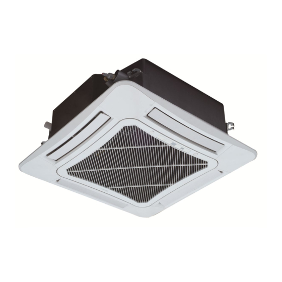
Cassette B Series
MODELS:
CAS12HP230V1BC
CAS18HP230V1BC
CAS24HP230V1BC
G R E E C O M F O R T . C O M
Thank you for choosing our product.
Please read this Installation & Owner's Manual carefully before
operation and retain it for future reference.
If you lose this Manual, please contact your local distributor
visit
www.greecomcomfort.com/resources
file the electronic version.
Service Manual
now to download an
Advertisement
Table of Contents

Related Manuals for Gree CAS12HP230V1BC


Summary of Contents for Gree CAS12HP230V1BC
- Page 1 Service Manual Cassette B Series MODELS: Thank you for choosing our product. Please read this Installation & Owner’s Manual carefully before CAS12HP230V1BC operation and retain it for future reference. CAS18HP230V1BC CAS24HP230V1BC If you lose this Manual, please contact your local distributor visit www.greecomcomfort.com/resources...
- Page 2 Multi-zone Cassette B Installation, Service & Troubleshooting Models: CAS12HP230V1BC CAS18HP230V1BC CAS24HP230V1BC...
-
Page 3: Table Of Contents
Service Manual Table of Contents Part Ⅰ : Technical Information ................1 1. Summary ........................1 2. Specifications ......................2 2.1 Specification Sheet ......................2 3. Outline Dimension Diagram ................5 4. Refrigerant System Diagram ..............6 5. Electrical Part ......................7 5.1 Wiring Diagram .........................7 5.2 PCB Printed Diagram .......................9 6. - Page 4 Service Manual Appendix: ........................49 Appendix 1: Reference Sheet of Celsius and Fahrenheit ............49 Appendix 2: Configuration of Connection Pipe ..............49 Appendix 3: Pipe expanding Method ...................50 Appendix 4: List of Resistance for Temperature Sensor ............51 Table of Contents...
-
Page 5: Part Ⅰ : Technical Information
Service Manual Part Ⅰ : Technical Information 1. Summary Indoor Unit CAS12HP230V1BC CAS18HP230V1BC CAS24HP230V1BC Remote Controller YAP1FFB Technical Information... -
Page 6: Specifications
Service Manual 2. Specifications 2.1 Specification Sheet Parameter Unit Value Model CAS12HP230V1BC CAS18HP230V1BC Product Code CN510N0190_X20047 CN510N0210_X20047 Rated Voltage 208/230 208/230 Power Rated Frequency Supply Phases Cooling Capacity Btu/h 12000 14400 Heating Capacity Btu/h 13000 16000 Air flow volume(H/M/L/SL) 330/306/265/-... - Page 7 Service Manual Parameter Unit Value Model CAS24HP230V1BC Product Code CN510N0200_X20047 Rated Voltage 208/230 Power Rated Frequency Supply Phases Cooling Capacity Btu/h 22800 Heating Capacity Btu/h 27400 Air flow volume(H/M/L/SL) 718/647/518/- Dehumidifying Volume Pint/h 5.28 Fan Type Centrifugal Fan Diameter-height inch Φ17 11/16-5 5/8 Fan Motor Cooling Speed(SH/H/M/L/SL) 650/620/560/450/-...
- Page 8 Service Manual Note: Nominal capacities are based on the follow conditions. Mode Indoor Outdoor DB:80.6(27) DB:95(35) Cooling WB:66.2(9) WB:75.2(24) DB:68 (20) DB:44.6(7) Heating WB:--(--) WB:42.8(6) Piping Length 3/16 inch The air volume is measured at the relevant standard external static pressure. Noise is tested in the semianechoic room, so it should be slightly higher in the actual operation due to environmental change.
-
Page 9: Outline Dimension Diagram
Service Manual 3. Outline Dimension Diagram CAS12HP230V1BC CAS18HP230V1BC CAS24HP230V1BC Unit: inch Item Model CAS12HP230V1BC 26 3/8 26 1/4 23 5/8 19 1/2 5 11/16 9 7/16 23 7/16 CAS18HP230V1BC CAS24HP230V1BC 37 3/8 33 1/16 30 11/16 26 3/4 5 11/16... -
Page 10: Refrigerant System Diagram
Service Manual 4. Refrigerant System Diagram Technical Information... -
Page 11: Electrical Part
Jumper cap Yellow Brown COMP Compressor Blue Grounding wire YEGN Yellow/Green Black Violet Orange Note: Jumper cap is used to determine fan speed and the swing angle of horizontal lover for this model. ● Indoor Unit CAS12HP230V1BC CAS18HP230V1BC 600007061910 Technical Information... - Page 12 Service Manual CAS24HP230V1BC 600007061911 These circuit diagrams are subject to change without notice, please refer to the one supplied with the unit. Technical Information...
-
Page 13: Pcb Printed Diagram
Service Manual 5.2 PCB Printed Diagram Top view Name Interface of fan Interface of live wire Fuse Interface of netural wire Air terminal Terminal with outdoor unit communication wire Water pump control Interface of ambient temperature sensor Interface of tube temperature sensor 10 Water full detection terminal Up&down swing motor 12 Jumper cap terminal... -
Page 14: Function And Control
Service Manual 6. Function and Control 6.1 Remote Controller Introduction ON/OFF button MODE button FAN button TURBO button ▲/ button button button T-ON / T-OFF button I FEEL button CLOCK button SLEEP button X-FAN button (Note: X-FAN is the same with BLOW.) button LIGHT button TEMP button... - Page 15 Service Manual 1. ON/OFF button Press this button to turn on the unit. Press this button again to turn off the unit. 2. MODE button Press this button to select your required operation mode. AUTO COOL HEAT When selecting auto mode, air conditioner will operate automatically according to the sensed temperature. Set temperature can’t be adjusted and will not be displayed as well.
- Page 16 Service Manual When selecting " ", air conditioner is blowing fan automatically. Horizontal louver will automatically swing up & down at maximum angle. When selecting " ", air conditioner is blowing fan at fixed position. Horizontal louver will stop at the fixed position. When selecting "...
- Page 17 Service Manual button Press this button to achieve the on and off of healthy and scavenging functions in LCD displays " ". Press the button for the second time to start healthy and scavenging functions simultaneously; LCD displays " " and " ".
- Page 18 Service Manual WIFI Function Press "MODE" and "TURBO" button simultaneously to turn on or turn off WIFI function. When WIFI function is turned on, the " WiFi" icon will be displayed on remote controller; Long press "MODE" and "TURBO" buttons simultaneously for 10s, remote controller will send WIFI reset code and then the WIFI function will be turned on.
-
Page 19: Brief Description Of Modes And Functions
Service Manual 6.2 Brief Description of Modes and Functions 1.Basic function of system (1)Cooling mode (1) Under this mode, fan and swing operates at setting status. Temperature setting range is 61-86°F(16~30 (2) During malfunction of outdoor unit or the unit is stopped because of protection, indoor unit keeps original operation status. (2)Drying mode (1) Under this mode, fan operates at low speed and swing operates at setting status. - Page 20 Service Manual (8)I feel control mode After controller received I feel control signal and ambient temperature sent by remote controller, controller will work according to the ambient temperature sent by remote controller. (9)Compulsory defrosting function (1) Start up compulsory defrosting function Under ON status, set heating mode with remote controller and adjust the temperature to 61(16 C).
- Page 21 Service Manual (17)Instructions to the Error Indicating Lamps on the Panel of the Cassette Type Unit. Receiver "88" Dispaly" Auto" Button Timer Power "Test" Button Indicating Lamp Indicating Lamp Power and ON/OFF Indicating Lamp: It goes red when the unit is powered on while it goes white when the unit is started. Timer Indicating Lamp: Timer indicator on indoor unit will be on when timer ON is set under off status and timer OFF is set under on status.
-
Page 22: Part Ⅱ : Installation And Maintenance
Service Manual Part Ⅱ : Installation and Maintenance 7. Notes for Installation and Maintenance Safety Precautions: 10. If the power cord or connection wire is not long enough, please get the specialized power cord or connection wire Important! from the manufacture or distributor. Prohibit prolong the wire by yourself. - Page 23 Service Manual Safety Precautions for Installing and Relocating the Unit: To ensure safety, please be mindful of the following precautions. Warnings 1. When installing or relocating the unit, be sure to keep the refrigerant circuit free from air or substances other than the specified refrigerant.
- Page 24 Service Manual Main Tools for Installation and Maintenance 1. Level meter, measuring tape 2. Screw driver 3. Impact drill, drill head, electric drill 4. Electroprobe 5. Universal meter 6. Torque wrench, open-end wrench, inner hexagon spanner 7. Electronic leakage detector 8.
-
Page 25: Installation
Service Manual 8. Installation 8.1 Installation Dimension Diagram Indoor Installation and Maintenance... -
Page 26: Preparative For Installation
Service Manual 8.2 Preparative for Installation 8.2.1 Standard Accessory Parts The standard accessory parts listed below are furnished and should be used as required. Table 1 Indoor Unit Accessories Name Appearance Q'ty Usage To connect with the hard PVC drain Drain Hose pipe Nut with Washer... -
Page 27: Installation Of Cassette Type
Confirm if the installing foundation is solid. When this Models H(inch) unit is to be installed on the metal section of CAS12HP230V1BC 10 1/16 the building, make sure that the electrical insulation CAS18HP230V1BC must comply with applicable standards. CAS24HP230V1BC... -
Page 28: Installation Of The Connection Pipe
Service Manual 8.3.7. Leveling Notes: The fuse is located on the main board. Install the disconnect device with a contact gap of at least 3mm in all poles nearby the units The water level test must be done after installing the indoor unit (Both indoor unit and outdoor unit).The appliance must be positioned so that the plug is accessible. - Page 29 Service Manual Table 4 Flare nut tightening torque CAUTION! Pipe Diameter Tightening Torque To prevent breaking of the pipe, avoid sharp bends. Bend the 1/4˝(Inch) 15-30 (N·m) pipe with a radius of curvature of 150mm or over. 3/8˝(Inch) 35-40 (N·m) If the pipe is bent repeatedly at the same place, it will break.
-
Page 30: Installation Of The Drain Hose
Service Manual gauge manifold If the outdoor unit is installed higher than the indoor unit (See Fig.13 pipe (1). Taping should be done from Low pressure gauge lower to the upper part. High pressure gauge Gauge manifold kit (2). All pipes are bound and taped pipe VAC valve together and also should be... -
Page 31: The Panel Installation
Service Manual (4). Secure a downward gradient of 1/100 or more for the drain (3). When unifying multiple drain pipes, install the pipes as Fig.16. pipe.To accomplish this, mount supporting brackets at an Select converging drain pipes whose gauge is suitable for the operating interval of 39 3/8 - 59 1/16 inch. -
Page 32: Electrical Wiring
Service Manual 8.7 Electrical Wiring (2). Improper screwing of the screws may cause the troubles shown in Fig.28. 8.7.1 Wiring Precautions WARNING! Before obtaining access to terminals, all supply circuits must be disconnected. The rated voltage of the unit is as shown as Table 4 Before turning on, verify that the voltage is within the Condensate 198~264V range(for single phrase unit) or 342~457V... -
Page 33: Installation Of Controrllers
Service Manual 24k: Power supply terminal board Fig.33 After passing the connection cord fasten it with the cord c lamp.(Fig.33) WARNING! Seal here to avoid leakage Before starting work, check that power is not being supplied to the indoor unit and outdoor unit. Match the terminal block numbers and connection cord colors with those of the indoor unit side. -
Page 34: Maintenance
Service Manual 9. Maintenance 9.1 Error Code List If cut-off of water level switch is detected for 8s successively once Full water Water level energized, the system will enter protection switch full water protection. In this case, switch off the unit and then switch it on to eliminate this malfunction. -
Page 35: Troubleshooting For Main Malfunction
Service Manual 9.2 Troubleshooting for Main Malfunction ●Indoor unit: 1. Malfunction of Temperature Sensor F1, F2 Main detection points: ● Is the wiring terminal between the temperature sensor and the controller loosened or poorly contacted? ● Is there short circuit due to trip-over of the parts? ●... - Page 36 Service Manual 2. Malfunction of Blocked Protection of IDU Fan Motor H6 Start Turn the fan blades by hand under power-off condition Adjust the motor and blade Whether the fan blades assembly so that rotor can run can run smoothly? smoothly.
- Page 37 Service Manual 3. Malfunction of Protection of Jumper Cap C5 Main detection points: ● Is there jumper cap on the mainboard? ● Is the jumper cap inserted correctly and tightly? ● The jumper is broken? ● The motor is broken? ●...
- Page 38 Service Manual 4. Communication malfunction E6 Start Cut off power supply. Check if connection line of IDU and ODU and the wire inside electric box are correctly connected. Connect the line Correct connection? according to Malfunction eliminated? wiring diagram. Main board matches Match correctly with display board? Main board of Malfunction eliminated?
- Page 39 Service Manual Troubleshooting for F0 malfunction Heat exchangers are Clean the heat exchangers and remove Malfunction is too dirty or the air inlet/outlet eliminated. blockage of air inlet/outlet. is blocked. Compressor doesn't work Malfunction is Make compressor run normally. normally. Strange noise or leakage occurs. eliminated.
- Page 40 Service Manual 6. Full Water Protection E9 Installation and Maintenance...
-
Page 41: Maintenance Method For Normal Malfunction
Service Manual 9.3 Maintenance Method for Normal Malfunction 1. Air Conditioner Can't be Started Up Possible Causes Discriminating Method (Air conditioner Status) Troubleshooting Confirm whether it's due to power failure. If yes, No power supply, or poor After energization, operation indicator isn’t bright wait for power recovery. - Page 42 Service Manual 4. ODU Fan Motor Can't Operate Possible causes Discriminating method (air conditioner status) Troubleshooting Connect wires according to wiring diagram to Wrong wire connection, or poor Check the wiring status according to circuit make sure all wiring terminals are connected connection diagram firmly...
-
Page 43: Exploded View And Parts List
Service Manual 10. Exploded View and Parts List CAS12HP230V1BC The component picture is only for reference; please refer to the actual product. Installation and Maintenance... - Page 44 Service Manual Part Code Description CAS12HP230V1BC Product Code CN510N0190_X20047 Rear Grill 26909400007 Brushless DC Motor 1570940000401 Water Tray Assy 01289400004 Water Pump 4313800005801 Supporter 01809400007 Water Level Switch 450102013 Pump Drainpipe 26909400069 Water Pump Assy 15409400008 Right Side Plate Sub-Assy...
- Page 45 Service Manual CAS18HP230V1BC The component picture is only for reference; please refer to the actual product. Installation and Maintenance...
- Page 46 Service Manual Part Code Description CAS18HP230V1BC Product Code CN510N0210_X20047 Rear Grill 26909400007 Brushless DC Motor 1570940000401 Water Tray Assy 01289400004 Water Pump 4313800005801 Supporter 01809400007 Water Level Switch 450102013 Pump Drainpipe 26909400069 Water Pump Assy 15409400008 Right Side Plate Sub-Assy 01319400013 Bottom Foam Assy 12509400004...
- Page 47 Service Manual CAS24HP230V1BC The component picture is only for reference; please refer to the actual product. Installation and Maintenance...
- Page 48 Service Manual Part Code Description CAS24HP230V1BC Product Code CN510N0200_X20047 Electric Box Assy 100002066223 Terminal Board 420001000002 Electric Base Plate 01412721 Water Tray Assy 000069000104 Fan Fixer 10312701 Centrifugal Fan 10312705 Evaporator Assy 011001060292 Left Side Plate Assy 01302715 Front Side Plate assy 01302718 Base Plate Assy 01222701...
-
Page 49: Removal Procedure
Service Manual 11. Removal Procedure Warning: Be sure to wait for a minimum of 20 minutes after turning off all power supplies and discharge the refrigerant completely before removal. 1. Unscrew the water tray. Use a screwdriver to unscrew the water tray. 2. - Page 50 Service Manual 4. Remove the centrifugal fan. Remove the centrifugal fan. 5. Unscrew the motor. Use a screwdriver to unscrew the motor. 6. Replace the motor with a new one Replace the motor with a new one. 7. Screw the motor. Use a screwdriver to screw the motor.
- Page 51 Service Manual 8. Install and screw the centrifugal fan. Install the centrifugal fan and use a wrench to screw the centrifugal fan. 9. Install and screw the water tray. Use a screwdriver to screw the water tray 9. pump Unscrew the water tray. Use a screwdriver to unscrew the water tray.
- Page 52 Service Manual Remove the drainage duct nscrew the pump. Remove the drainage duct and use a screwdriver to unscrew the pump. Replace the pump. Connect the drainage duct and screw the new pump. Connect the drainage duct and use a screwdriver to screw the new pump.
-
Page 53: Appendix
Service Manual Appendix: Appendix 1: Reference Sheet of Celsius and Fahrenheit Conversion formula for Fahrenheit degree and Celsius degree: Tf=Tcx1.8+32 Set temperature Fahrenheit Fahrenheit Fahrenheit display Fahrenheit display Fahrenheit display Fahrenheit Celsius( Celsius( Celsius( temperature temperature temperature 60.8 69/70 69.8 78/79 78.8 62/63... -
Page 54: Appendix 3: Pipe Expanding Method
Service Manual Appendix 3: Pipe Expanding Method Pipe Note: Pipe cutter Improper pipe expanding is the main cause of refrigerant leakage.Please expand the pipe according to the following steps: Leaning Uneven Burr A:Cut the pip ● Confirm the pipe length according to the distance of indoor unit and outdoor unit. ●... -
Page 55: Appendix 4: List Of Resistance For Temperature Sensor
Service Manual Appendix 4: List of Resistance for Temperature Sensor Resistance Table of Ambient Temperature Sensor for Indoor and Outdoor (15K) Temp( C) Resistance(kΩ) Temp( C) Resistance(kΩ) Temp( Resistance(kΩ) Temp( Resistance(kΩ) 138.1 18.75 3.848 1.071 128.6 17.93 3.711 1.039 121.6 17.14 3.579 1.009... - Page 56 Service Manual Resistance Table of Tube Temperature Sensors for Outdoor and Indoor (20K) Temp( C) Resistance(kΩ) Temp( C) Resistance(kΩ) Temp( Resistance(kΩ) Temp( Resistance(kΩ) 181.4 25.01 5.13 1.427 171.4 23.9 4.948 1.386 162.1 22.85 4.773 1.346 153.3 21.85 4.605 1.307 20.9 4.443 1.269 137.2...
- Page 57 Service Manual Resistance Table of Discharge Temperature Sensor for Outdoor (50K) Temp( C) Resistance(kΩ) Temp( Resistance(kΩ) Temp( C) Resistance(kΩ) Temp( Resistance(kΩ) 853.5 18.34 4.75 799.8 93.42 17.65 4.61 89.07 16.99 4.47 703.8 84.95 16.36 4.33 660.8 81.05 15.75 4.20 620.8 77.35 15.17 4.08...
- Page 58 U.S. CONTACT INFORMATION TRADEWINDS, LLC E-mail: info@twclimate.com Contractor Support: 888-850-7928 | Mon-Fri 8 AM - 5 PM EDT www.greecomfort.com/system-documentation/ GREE ELECTRIC APPLIANCES, INC. OF ZHUHAI Add: West Jinji RD, Qianshan, Zhuhai, Guangdong, China, 519070 Tel: (+86-756) 8522218 Fax: (+86-756) 8669426 E-mail: gree@gree.com.cn...
Need help?
Do you have a question about the CAS12HP230V1BC and is the answer not in the manual?
Questions and answers