Advertisement
Quick Links
Interface Manual
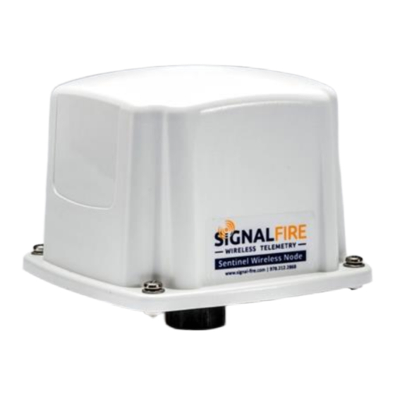
Sentinel Float Scout
The SignalFire Sentinel Float Stick Node is an Intrinsically Safe device with the
following features:
-
Standard SignalFire Sentinel RS485-Modbus Node
-
RS485 connection to internal Float Stick Interface Board
-
1 or 2 floats with temperature(s) supported
-
Low power operation from an intrinsically safe high capacity lithium primary
battery pack
-
Optional solar battery system for routing nodes or rapid data collection
-
Sends data to a SignalFire Buffered Modbus Gateway
-
AES 128bit encryption
Rev 1.2
SignalFire Model: Sentinel-FS-3BIS
SignalFire Telemetry
1
Advertisement

Subscribe to Our Youtube Channel
Summary of Contents for SignalFire Sentinel-FS-3BIS
- Page 1 Interface Manual Sentinel Float Scout SignalFire Model: Sentinel-FS-3BIS The SignalFire Sentinel Float Stick Node is an Intrinsically Safe device with the following features: Standard SignalFire Sentinel RS485-Modbus Node RS485 connection to internal Float Stick Interface Board 1 or 2 floats with temperature(s) supported...
-
Page 2: Specifications
Specifications Enclosure Size 3.5” tall × 5.0” wide × 5.0” deep Power Source Internal IS Lithium battery pack SignalFire Part Number: 3BIS External Solar battery system SignalFire Part Number: Sentinel-HCSolar DC-DC Converter SignalFire Part Number: DCDC-Sentinel Other external power supply meeting the power entity parameters from the control drawing. -
Page 3: Connections And Components
The ERROR LED (red) will blink to indicate an error condition. Scan/Checkin Button If this button is pressed the Sentinel will take a reading from the Float Stick and send those values to the gateway. Rev 1.2 SignalFire Telemetry... - Page 4 Network selection/Encryption settings Check-in period selection Float Stick mode enable All settings are made using the SignalFire Toolkit PC application and a serial programming cable. WARNING: Perform the steps in this section (Setup) in a safe location only. Using the SignalFire Toolkit The SignalFire Toolkit application can be downloaded at www.signal-fire.com/customer.
- Page 5 To set up a legacy Sentinel to use encryption, click the checkbox labeled Enable Encryption inside the Set Corporate ID box. All newer Sentinels come with this option enabled with “signalfire” as the default encryption key. Corporate ID...
- Page 6 Sentinel type for Float Stick operation if it is in the default Modbus mode. To do this, select Float Stick in the Set Sentinel Type option under the Settings pull down menu. Rev 1.2 SignalFire Telemetry...
-
Page 7: Sensor Connections
To ensure intrinsic safety is maintained it is required that the installer follow these guidelines when connecting sensors to the SignalFire node. See pictures for proper wire routing examples. Strip the wires so that there is minimal exposed un-insulated wire when inserted into the screw terminal. - Page 8 Optionally a “Level Cutoff” setting can be set for the product and/or level readings. Any reading at or below the configured cutoff setting will be reported as zero. This is useful as the float cannot reach the actual bottom of the tank due to the weight and required spacing. Rev 1.2 SignalFire Telemetry...
- Page 9 Remote Modbus Register Mapping The Sentinel Node sends data to a SignalFire Telemetry Modbus Gateway. The data that is sent to the gateway is available at the gateway in registers where it can then be read by a Modbus RTU.
- Page 10 In addition, a ¾” NPT compression fitting is supplied for mounting the assembly to a tank. Sentinel Mounting to Float Stick ½” NPT Nipple (supplied) ½” to ¾” NPT Adapter (supplied) FLOAT STICK 1" NPT Compression Fitting (ordered separately) Rev 1.2 SignalFire Telemetry...
- Page 11 Note: For dual float systems the lower float is marked with an “I” and the upper float is marked with a “P”. For dual floats the foam float spacer is required between the floats. Rev 1.2 SignalFire Telemetry...
- Page 12 Connect the battery to the main PCB battery connector. Install the enclosure cover. WARNING: Use of any battery other than the SignalFire part number 810-0008-02 will impair the protection provided by the equipment. WARNING: If the internal battery is installed the external solar battery system or other...
- Page 13 Debug and configuration information is available if a connection is made via the debug port on the main board. A USB converter cable (available from SignalFire) must be used for this interface. Debug and advanced configuration may be done using the SignalFire Toolkit PC application.
- Page 14 APPENDIX - FCC and IC Statements Changes or modifications not expressly approved by SignalFire Telemetry, Inc could void the user’s authority to operate the equipment. This device complies with Part 15 of the FCC Rules. Operation is subject to the following two conditions: (1) this device may not cause harmful interference, and (2) this device must accept any interference received, including interference that may cause undesired operation.


Need help?
Do you have a question about the Sentinel-FS-3BIS and is the answer not in the manual?
Questions and answers