Advertisement
Quick Links
Interface Manual
Modbus Multi I/O Module
The SignalFire Modbus Multi I/O Module has the following features:
-
Standard Modbus RTU server device
-
Can be read with a SignalFire Modbus Stick or another Modbus client
-
8 analog inputs (0-20mA or 0-5V)
-
6 digital inputs (state, counter, and frequency up to 2kHz)
-
4 relay outputs (2 DPDT, 2 SPST)
-
Internal relay control logic for shutdown applications
-
Wide range DC power input. 6 to 36VDC
-
Very low power consumption
-
DIN Rail mount with pluggable screw terminal blocks
-
Status LEDs
-
Analog scaling configuration
Rev 1.8
SignalFire Number: MIOM
SignalFire Telemetry
1
Advertisement

Subscribe to Our Youtube Channel
Related Manuals for SignalFire MIOM


Summary of Contents for SignalFire MIOM
- Page 1 The SignalFire Modbus Multi I/O Module has the following features: Standard Modbus RTU server device Can be read with a SignalFire Modbus Stick or another Modbus client 8 analog inputs (0-20mA or 0-5V) 6 digital inputs (state, counter, and frequency up to 2kHz)
-
Page 2: Specifications
(excludes current for attached analog sensors) Operating Temp -40°C to +80°C Analog Inputs 0-10V Max Digital Inputs Dry Contact or 30 Volts Max Modbus Comm Modbus RTU Server Relay Rating 30 VDC @ 2 Amps 250 VAC @ 0.25 Amps Rev 1.8 SignalFire Telemetry... -
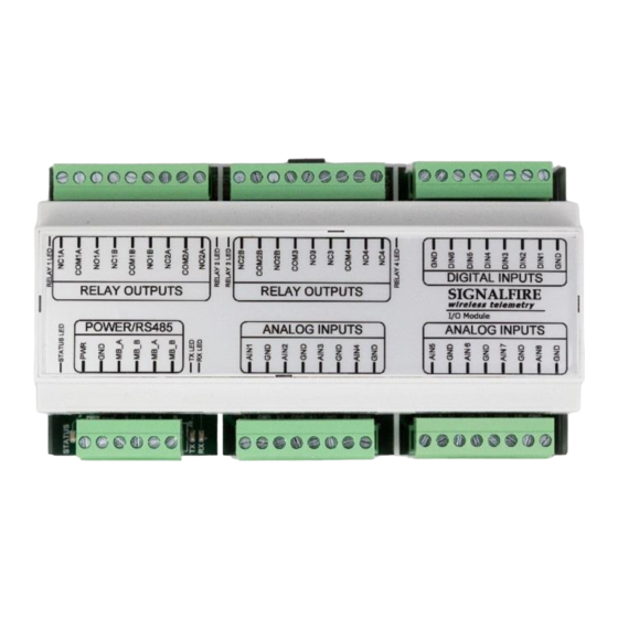
Page 3: Connections And Components
The Modbus Multi I/O has a green status LED which blinks indicating the module is running. In addition there are TX/RX LEDs to indicate RS485 messages to/from the Modbus Client. Each relay output also has a green LED which turns on while the relay is energized. Rev 1.8 SignalFire Telemetry... - Page 4 SignalFire Toolkit Configuration Connect to the internal 4-pin connection using a SignalFire USB adapter cable. The module will be auto-detected by the Toolkit. If the module is running “Multi IO System” firmware it must be loaded with the “Modbus Multi IO Module” to support Modbus functionality.
-
Page 5: Operation
Operation The SignalFire Modbus Multi I/O Module is intended to be used as a Modbus interfaced analog and digital input/output (I/O) unit. It allows the user to interface to a variety of sensor or control devices from a single Modbus port. It is DIN rail mounted and designed to be easy to use. - Page 6 DIP switch or via software. If the DIP switch is set to zero then the Server ID must be configured in software using either the SignalFire Toolkit or a Modbus write. The DIP switch must be set to 0 to be configured with the SignalFire Toolkit.
- Page 7 250 VAC @ 0.25 Amps Relay Failsafe Timers The MIOM supports a configurable failsafe timer which is used to de-energize selected relays in event of a communication failure. Relay Message Failsafe Timer – This timer is reset anytime a coil write for any Modbus relay coil write is received.
- Page 8 Hazardous Location Certification The MIOM Module is rated Class 1 Division 2 non-incendive. Hudson, MA www.signal-fire.com 6 – 36 VDC Voltage: Current: 100 mA Max Temperature: –40ºC to +85ºC Intertek 4003827 Certified to CSA C22.2 No. 142 and CSA C22.2 No. 213 Conforms to ISA 12.12.01 and UL 916...
-
Page 9: Modbus Register Map
Counter5 Reset Coil 05, 15 00117 Counter6 Reset Coil 05, 15 Discretes (1xxxx) Read-only 11109 1108 DI1 State 11110 1109 DI2 State 11111 1110 DI3 State 11112 1111 DI4 State 11113 1112 DI5 State 11114 1113 DI6 State Rev 1.8 SignalFire Telemetry... - Page 10 03, 04 41127 1126 AI5: Scaled Reading 03, 04 41128 1127 AI5: Scaled Reading 03, 04 41129 1128 AI6: Scaled Reading 03, 04 41130 1129 AI6: Scaled Reading 03, 04 41131 1130 AI7: Scale Reading 03, 04 Rev 1.8 SignalFire Telemetry...
- Page 11 DI5: Counts per minute (x 10) 03, 04 41216 1215 DI6: Average Frequency (Hz x 10) 03, 04 41217 1216 DI6: Instantaneous Frequency (Hz x 10) 03, 04 41218 1217 DI6: Counts per minute (x 10) 03, 04 Rev 1.8 SignalFire Telemetry...
- Page 12 03, 04, 06, 16 41187 1186 DI4 Debounce Time in mS 03, 04, 06, 16 41188 1187 DI5 Debounce Time in mS 03, 04, 06, 16 41189 1188 DI6 Debounce Time in mS 03, 04, 06, 16 Rev 1.8 SignalFire Telemetry...
- Page 13 03, 04, 06, 16 42055 1254 AI3:Scale Adjust 03, 04, 06, 16 42056 1255 AI3:Scale Adjust 03, 04, 06, 16 42057 1256 AI4:Scale Adjust 03, 04, 06, 16 42058 1257 AI4:Scale Adjust 03, 04, 06, 16 Rev 1.8 SignalFire Telemetry...
- Page 14 03, 04, 06, 16 Relay Control Logic The Modbus MIOM supports local relay control logic if it is running firmware version r7 or later. The logic is similar to the RSD control logic in the SignalFire Gateway. Note: If more than one rule is assigned to the same Output Relay, then all of the rules must meet the energize condition for the relay to be energized.
- Page 15 Input Channel – One of the Analog or Digital input channels on the MIOM module is selected for each rule line. Current Input Value – Once the rules are write to the MIOM this column shows the current value of the input. Click the Update button to refresh.
Need help?
Do you have a question about the MIOM and is the answer not in the manual?
Questions and answers